Near-field acoustic holographic calibration and measurement method for impedance characteristic of planar sonar array
A technology of near-field acoustic holography and impedance characteristics, applied in radio wave measurement systems, climate sustainability, instruments, etc., can solve problems such as inaccurate monitoring results, unfavorable ship monitoring, and impact on ship operation.
- Summary
- Abstract
- Description
- Claims
- Application Information
AI Technical Summary
Problems solved by technology
Method used
Image
Examples
Embodiment 1
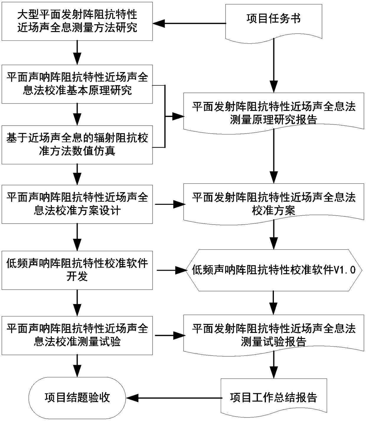
[0101] refer to figure 1 , the planar sonar array impedance characteristic near-field acoustic holography calibration measurement method in the present embodiment comprises the following steps:
[0102] a. Calculation method of impedance characteristics of planar emission array
[0103] The transmitter will be affected by the sound field while radiating sound waves, which is expressed as the force exerted by the medium close to the vibration surface, which is equal in value and opposite in direction to the force applied to the medium by the vibration surface, depending on the proximity The sound pressure in the medium on this surface, according to the integral of the sound pressure distribution on the emitting surface along the vibrating surface, the force of the medium on the vibrating surface can be obtained, and the sound pressure in the sound field is proportional to the particle velocity of the medium at this place, that is:
[0104] P=u·Z 0 (1)
[0105] It can be con...
Embodiment 2
[0263] In this embodiment, on the basis of Embodiment 1, the simulation analysis in step d includes the following aspects:
[0264] d1. Influence of sound field measurement geometric parameters on calibration results
[0265] (1) The influence of windowing function on the calibration result;
[0266] (2) Radius of holographic surface: 0.5λ~20λ;
[0267] (3) Measuring point spacing: 0.1λ~0.5λ;
[0268] (4) The distance between the holographic surface and the sample to be calibrated: 0.1λ~0.25λ;
[0269] (5) Spacing between double hydrophones: 0.05λ~0.5λ;
[0270] d2. Calibration error analysis under different sonar array structures
[0271] (1) Eight-element array (2×4): 2m×1.3m;
[0272] (2) Nine-element array (3×3): 3m×1m;
[0273] (3) Nine-element array (9×1): 1m×3m;
[0274] d3. Analysis of calibration errors caused by random measurement errors and systematic errors caused by environmental interference, electrical noise and other factors;
[0275] d4. Analysis of th...
Embodiment 3
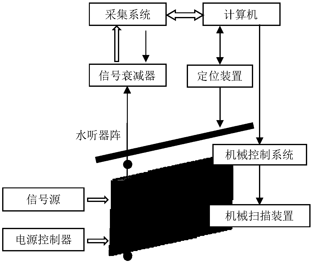
[0277] In this embodiment, on the basis of Embodiment 2, in the step F, it is necessary to build a calibration measurement system for the near-field acoustic holography of the impedance characteristics of the planar sonar array, specifically according to the established low-frequency planar sonar array impedance characteristic near-field acoustic holography theory Test the model and establish a near-field acoustic holographic multi-channel measurement system. The measurement receiving system is composed of a measurement hydrophone array, a signal attenuator, an acquisition system and a computer, such as figure 2 as shown,
[0278] (1), hydrophone array
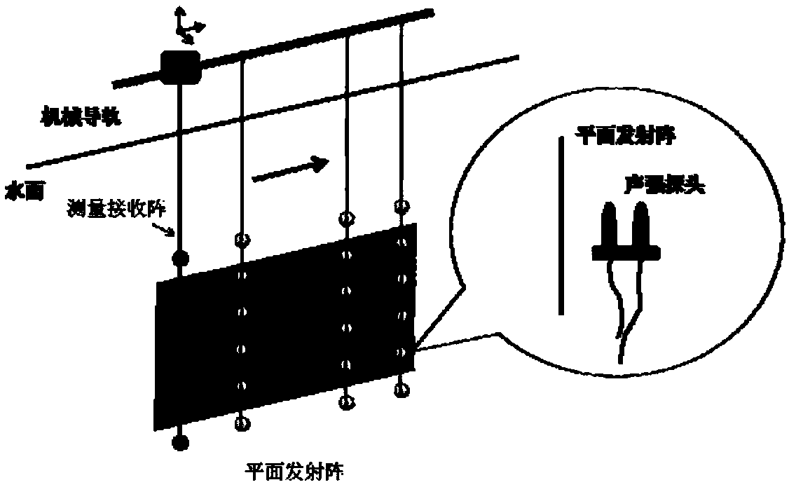
[0279] It consists of 32 hydrophones to form a measuring and receiving linear array; every two hydrophones constitute a set of sound intensity probes, a total of 16 pairs of sound intensity probes (or use 160 hydrophones to form 80 pairs of sound intensity probes, each pair of sound intensity Probe spacing is 20cm); 32 B&K81...
PUM
 Abstract
Description
Claims
Application Information
 - R&D
- Intellectual Property
- Life Sciences
- Materials
- Tech Scout
- Unparalleled Data Quality
- Higher Quality Content
- 60% Fewer Hallucinations
Browse by: Latest US Patents, China's latest patents, Technical Efficacy Thesaurus, Application Domain, Technology Topic, Popular Technical Reports.
© 2025 PatSnap. All rights reserved.Legal|Privacy policy|Modern Slavery Act Transparency Statement|Sitemap|About US| Contact US: help@patsnap.com


