A UWB Energy Selective Surface

An energy-selective, ultra-broadband technology, applied in the field of materials, can solve the problems of introducing noise into the system, unable to meet the needs of high-frequency electronic systems, etc., to achieve the effect of protection and safety

Active Publication Date: 2020-06-19
NAT UNIV OF DEFENSE TECH
View PDF9 Cites 6 Cited by
  • Summary
  • Abstract
  • Description
  • Claims
  • Application Information

AI Technical Summary

Problems solved by technology

Moreover, its passband is 0-2.4GHz, which will introduce a lot of noise into the system, which cannot meet the needs of high-frequency electronic systems

Method used


Image

  • A UWB Energy Selective Surface
  • A UWB Energy Selective Surface
  • A UWB Energy Selective Surface

Examples


Embodiment Construction

[0026] The present invention will be further described below in conjunction with drawings and embodiments.

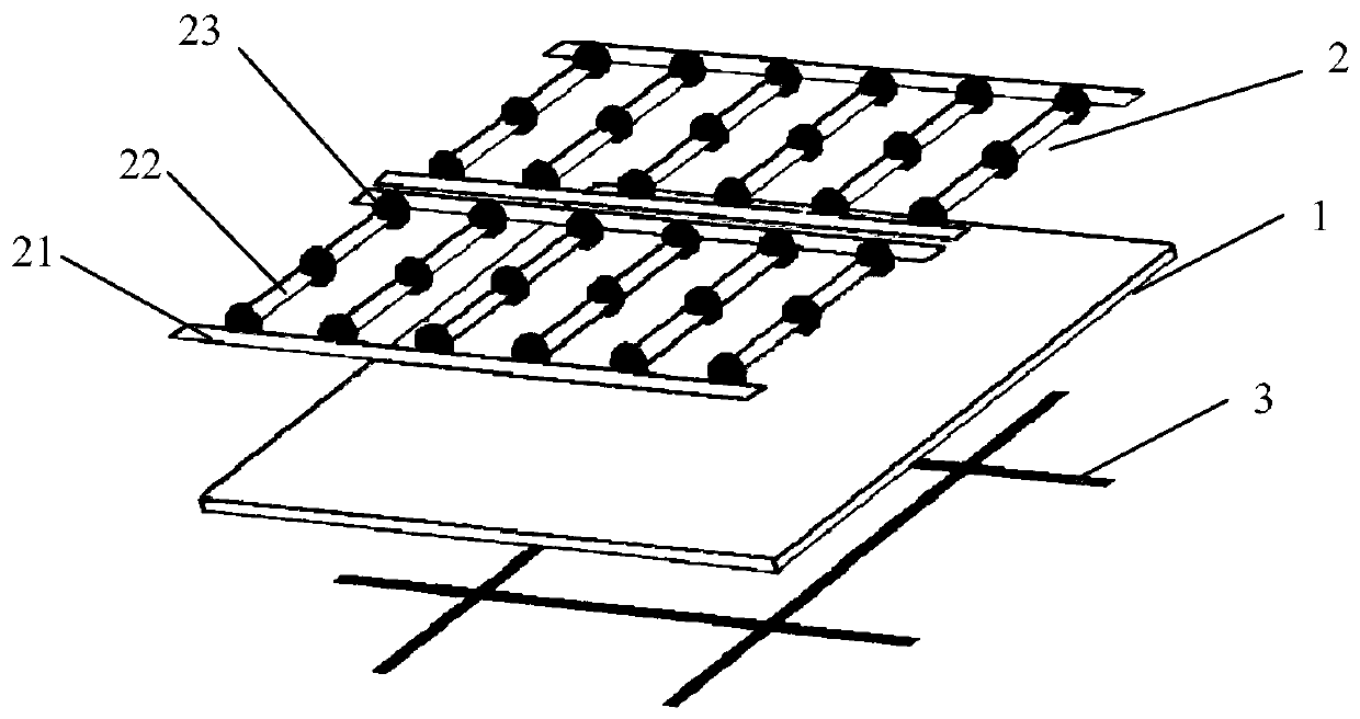
[0027] Such as figure 1 Shown is the structural diagram of the present invention. An ultra-broadband energy selective surface comprising a dielectric substrate, a first metal structure printed on the upper surface of the dielectric substrate, and a second metal structure printed on the lower surface of the dielectric substrate;

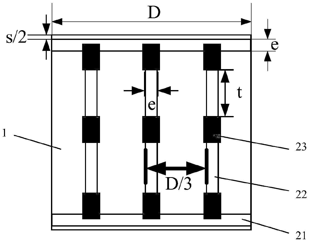
[0028] The first metal structure is two groups of identical orbital combined shapes; the orbital combined shape includes two parallel horizontal metal strips and several parallel vertical metal strips connecting the two horizontal metal strips. The vertical metal strips are arranged at equal intervals, and each vertical metal strip is loaded with several diodes;

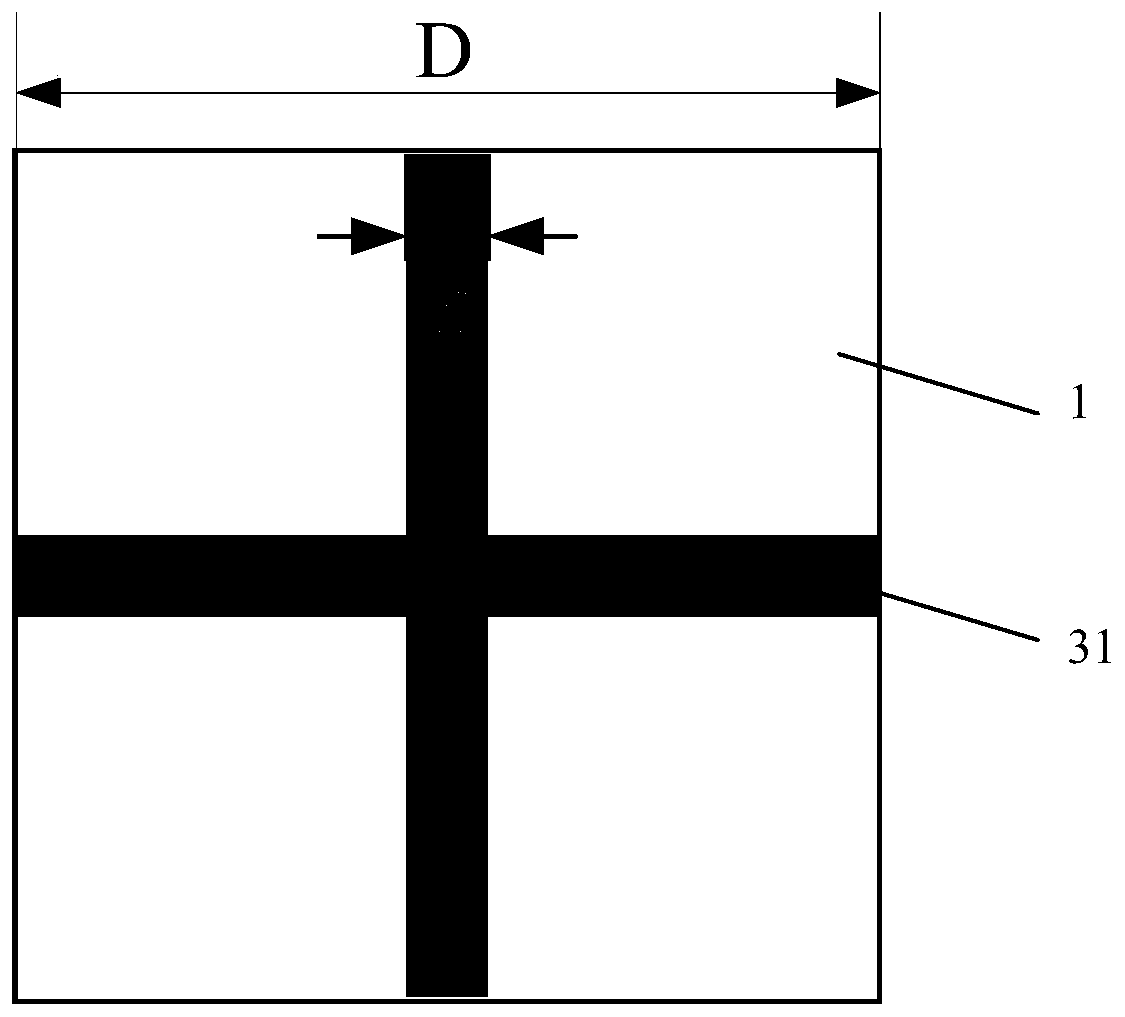
[0029] The second metal structure is a grid composed of metal strips.

[0030] In the embodiment, two sets of horizontal metal strips of the same orbital combined shape in the firs...


PUM

PropertyMeasurementUnit
thicknessaaaaaaaaaa

Abstract

The invention belongs to the technical field of the material, and specifically relates to an ultra wide band energy selection surface. The ultra wide band energy selection surface comprises a medium substrate, a first metal structure printed on an upper surface of the medium substrate, and a second metal structure printed on a lower surface of the medium substrate; the first metal structure is twogroups of same rail-mounted combination shapes; each rail-mounted combination shape comprises two mutually parallel cross metal strips and a plurality of mutually parallel longitudinal metal trips for connecting two cross metal strips; the longitudinal metal strips are arranged at intervals, and a plurality of diodes is loaded on each longitudinal metal strip; the second metal structure is a gridcomposed of the metal strips. The ultra wide band energy selection surface disclosed by the invention has the advantages that the multilayer metal periodic structure and the PIN diodes are used for realizing the frequency selection feature on incident electromagnetic wave and the energy selection feature for sending the electromagnetic energy, and the ultra wide band energy selection surface is anovel and self-adaptive front-door electromagnetic signal suppression technology.

Description

technical field [0001] The invention belongs to the technical field of materials, and in particular relates to an ultra-broadband energy selective surface. Background technique [0002] With the rapid development of electronic information technology, the degree of integration, intelligence and miniaturization of various electronic information equipment is continuously improved, its frequency is increasing day by day, energy consumption is also decreasing day by day, and its performance has been greatly improved. Given the complexity of the electromagnetic environment and the sensitivity and vulnerability of electronic information equipment to strong electromagnetic interference, the electromagnetic compatibility design of the system is facing unprecedented challenges. [0003] At present, the traditional electromagnetic compatibility design and strong electromagnetic pulse suppression methods mostly focus on "backdoor" suppression methods such as filtering, shielding and gro...

Claims


Application Information

Patent Timeline
Patent Type & Authority Patents(China)
IPC IPC(8): H05K9/00
CPCH05K9/0086
Inventor 王轲虎宁刘培国刘晨曦张继宏毋召锋刘翰青周奇辉戴上凯
Owner NAT UNIV OF DEFENSE TECH
Why Eureka
Try Eureka