Numerical control lathe capable of recycling cutting fluid

A technology for CNC lathes and cutting fluids, applied in the field of CNC lathes, can solve the problems of increasing mechanical operation steps, inconvenient observation, weak light, etc., and achieve the effects of reducing accidents, facilitating cleaning work, and simple mechanical operation

Active Publication Date: 2019-03-12
SUZHOU CHANGHENG PRECISION METAL DIE CASTING
View PDF8 Cites 17 Cited by
  • Summary
  • Abstract
  • Description
  • Claims
  • Application Information

AI Technical Summary

Problems solved by technology

[0006] 1. After the processing of the existing CNC lathe, the cutting fluid cannot be filtered and collected in time
[0007] 2. The existing CNC lathes tend to scatter cutting fluid and iron filings at the bottom of the lathe during processing, which is very inconvenient for cleaning
[0008] 3. The cutting fluid of the existing CNC lathe needs to be connected with an external container for the cutting fluid, which increases the mechanical operation steps and makes it more troublesome to control the machine
[0009] 4. When the existing CNC lathe is being processed, the light in the processing room is weak, the field of view is not sufficient, and it is inconvenient to observe.
[0010] 5. After the processing of the existing CNC lathe, since the waste box is usually fixed, the staff needs to use tools to clean the iron scraps from the bottom of the machine. This method is very inconvenient and increases the fatigue of the staff

Method used


Image

  • Numerical control lathe capable of recycling cutting fluid
  • Numerical control lathe capable of recycling cutting fluid
  • Numerical control lathe capable of recycling cutting fluid

Examples


Embodiment Construction

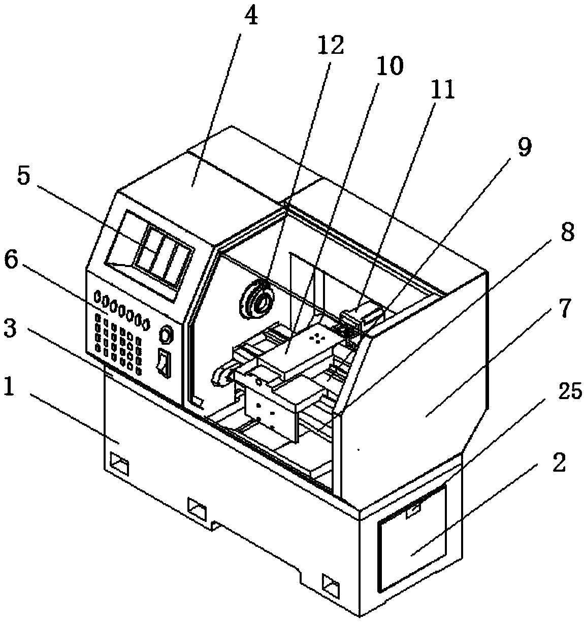
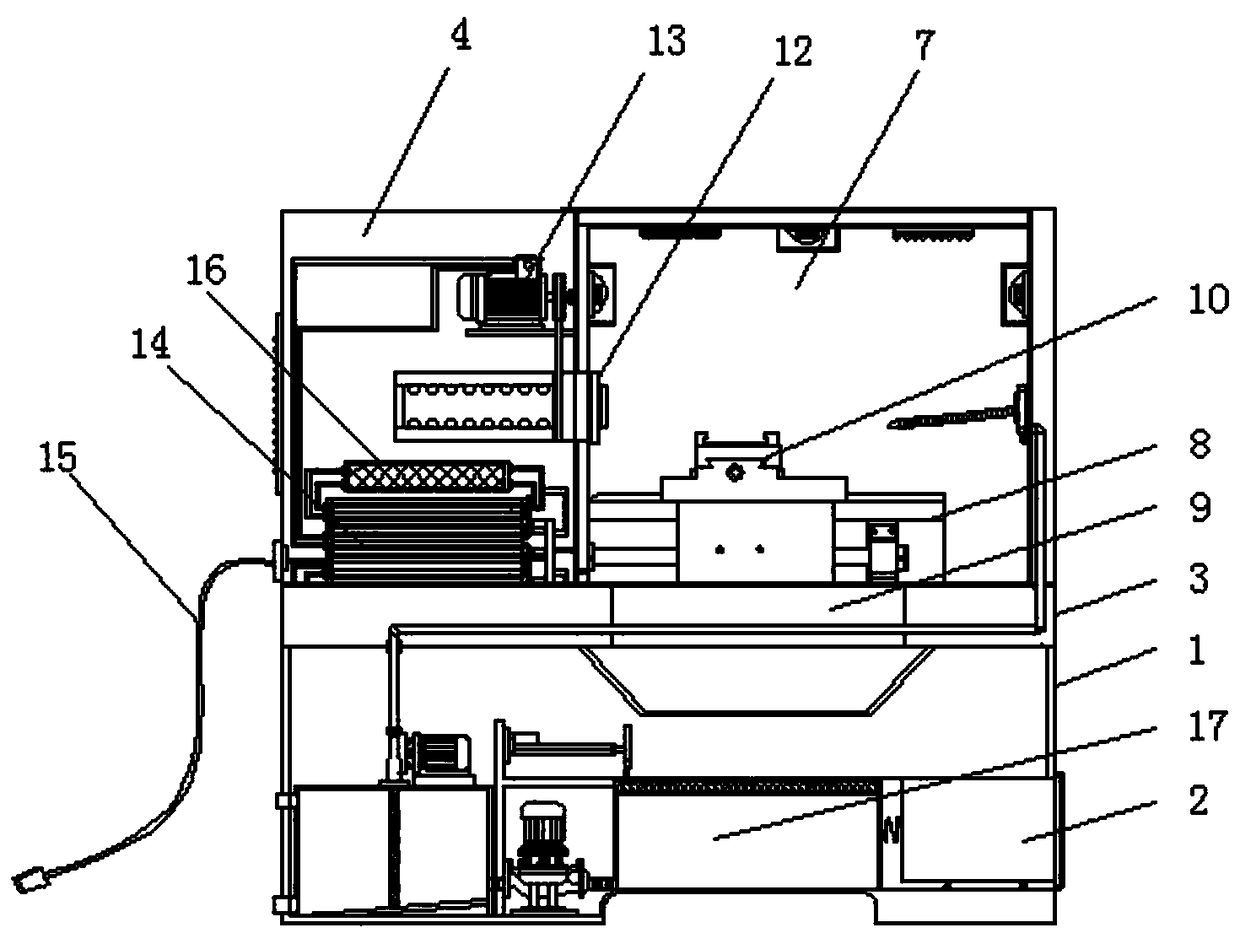
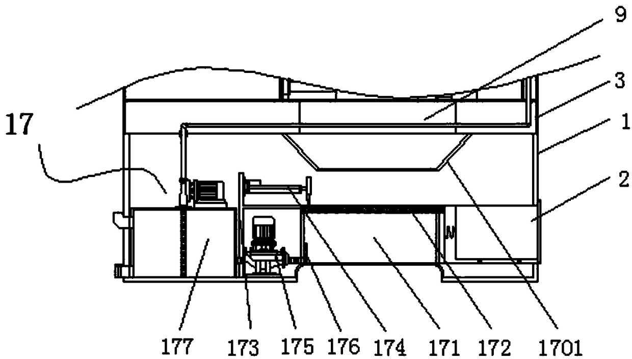
[0056] The following will be combined with Figure 1-9 The present invention is described in detail, and the technical solutions in the embodiments of the present invention are clearly and completely described. Apparently, the described embodiments are only some of the embodiments of the present invention, not all of them. Based on the embodiments of the present invention, all other embodiments obtained by persons of ordinary skill in the art without making creative efforts belong to the protection scope of the present invention.

[0057] The present invention provides a CNC lathe with recyclable cutting fluid through improvement, including a bottom box 1, a waste box 2, a connecting seat 3, a chassis 4, a display screen 5, a control panel 6, a processing room 7, a slide rail 8, Through slot 9, workbench 10, first motor 11, clamper 12, second motor 13, storage power supply 14, power cord 15, single-chip microcomputer 16, cutting fluid recovery device 17, first camera 18, secon...


PUM


Abstract

The invention discloses a numerical control lathe capable of recycling cutting fluid. The numerical control lathe comprises a bottom box, a display screen, a processing chamber, a workbench, a first motor, a cutting fluid recycling device, a first camera, a second camera, a third camera and a light, wherein a waste box is arranged at the right end of the bottom box; a connection seat is welded tothe upper end of the bottom box; the cutting fluid is collected by a recycling tank through the filtration of a first filter screen; at the same time, iron filings are pushed into the waste box by a pushing mechanism so that the cutting fluid cannot be wasted and the iron filings cannot be scattered and can be convenient to remove subsequently; the collected cutting fluid is pumped into a liquid collecting tank by a first liquid suction pump through a second filter screen and is pumped by a second liquid suction pump to be conveyed to a hydrojet pipe to spray, so that after recycling, the effect of reusing is achieved; the first camera, the second camera and the third camera monitor processing conditions in a processing chamber in real time; and after being processed by a single chip microcomputer, the processing conditions are displayed on the display screen so that the worker can observe the processing conditions in real time.

Description

technical field [0001] The invention relates to the related field of numerical control equipment, in particular to a numerical control lathe with recyclable cutting fluid. Background technique [0002] CNC lathe is one of the most widely used CNC machine tools at present. It is mainly used for cutting the inner and outer cylindrical surfaces of shaft parts or disk parts, the inner and outer conical surfaces of arbitrary cone angles, the complex rotary inner and outer curved surfaces, cylinders, and conical threads, etc., and can perform grooving, drilling, reaming, and reaming. Holes and borings, etc., and when CNC lathes process parts, a lot of heat will be generated due to the direct contact between the cutting tool and the workpiece. If there is no timely heat dissipation treatment, the cutting deviation of the workpiece surface will be chaotic, and the cutting tool will also Direct damage will cause the CNC lathe to be unable to work directly. During processing, cutting...

Claims


Application Information

Patent Timeline
Patent Type & Authority Applications(China)
IPC IPC(8): B23Q11/00B23Q11/10
CPCB23Q11/00B23Q11/0042B23Q11/1069
Inventor 兰勇祯
Owner SUZHOU CHANGHENG PRECISION METAL DIE CASTING
Why Eureka
Try Eureka