System and method for online detecting life of CMP polishing pad

A polishing pad, life-span technology, applied in grinding/polishing equipment, parts of grinding machine tools, control of workpiece feed movement, etc., can solve the problem of inconsistent polishing pad wear, product yield and yield decline, and production efficiency. and other problems, to achieve the effect of improving the quality of flattening, making full use of it, and making small changes.

Inactive Publication Date: 2019-03-12
HANGZHOU ZHONGGUI ELECTRONICS TECH CO LTD
0 Cites 7 Cited by

AI-Extracted Technical Summary

Problems solved by technology

[0009] Among them, the disadvantage of methods 1 and 2 is that, due to fluctuations in parameters such as the speed of the polishing table, the speed of the polishing head, the flow rate of the polishing liquid, and the temperature, it is easy to cause the wear of the polishing pad under the same working time or the same number of planarized wafers Inconsiste...

Abstract

The invention relates to a system and a method for online detecting the life of a CMP polishing pad. According to the system and the method, the polishing pad provided with a groove is arranged on thesurface of a polishing table and rotates along with the polishing table; a wafer is pressed by a polishing head on the surface of the polishing pad, moves relative to the polishing table, and is subjected to flattening treatment; a light source and an optical detector are mounted on a component in a corresponding polishing area; a light beam is emitted by the light source to the surface of the polishing pad and reflected to the optical detector; and a signal from the optical detector is online received by a controller, the depth of the groove is calculated by the controller according to the strength of the signal, and the remaining working time of the polishing pad is judged by the controller. The invention further provides a method for online adjusting CMP process parameters based on polishing pad life detection. According to the remaining working time of the polishing pad, the CMP process parameters such as the flattening time, the rotating speed of the polishing table, the rotatingspeed of the polishing head, the pressure of the polishing head, the flow rate of a polishing fluid, the temperature of a polishing disc, and other factors capable of controlling the wafer flatteningremoval efficiency can be adjusted online, and then the wafer flattening efficiency and flattening quality can be improved.

Application Domain

Technology Topic

Optical detectorsOptical detector +5

Image

  • System and method for online detecting life of CMP polishing pad
  • System and method for online detecting life of CMP polishing pad
  • System and method for online detecting life of CMP polishing pad

Examples

  • Experimental program(1)

Example Embodiment

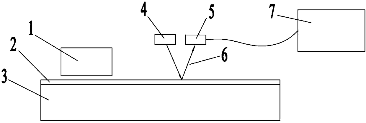
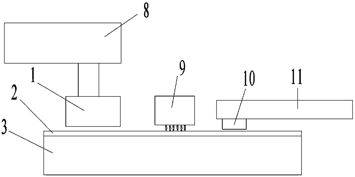
[0041] refer to figure 1 and figure 2 Shown, provide an embodiment of the online detection system of polishing pad life:
[0042] The system includes a polishing table 3 , the polishing pad 2 with grooves is pasted on the upper surface of the polishing table 3 and rotates together with the polishing table 3 . A light source 4 and an optical detector 5 are arranged above the polishing area. The light source 4 emits a light beam 6 to the surface of the polishing pad 2 and is reflected to the optical detector 5 by the surface of the polishing pad 2 .
[0043] The light source 4 and the optical detector 5 may be an integrated photoelectric sensor; or, the light source 4 and the optical detector 5 may be independent components.
[0044] A polishing head 1 carrying a wafer is arranged above the polishing table 3 , and the light source 4 and the optical detector 5 can be installed on a polishing arm 8 that fixes the polishing head 1 .
[0045] A nozzle for supplying polishing liquid to the upper surface of the polishing pad 2 is provided above the polishing table 3 , and the light source 4 and the optical detector 5 can be installed on a polishing liquid distributing arm 9 that fixes the nozzle.
[0046]The top of the polishing table 3 is provided with a trimming head 10 for trimming the surface of the polishing pad 2, and the light source 4 and the optical detector 5 can be installed on the trimming head 10, or installed on the trimming arm 11 that fixes the trimming head 10 superior.
[0047] The light source 4 and the optical detector 5 can be installed on other parts of the polishing area. The light source 4 emits the light beam 6 to the upper surface of the polishing pad 2 and then reflects to the optical detector 5 .
[0048] In one embodiment, the polishing table 3 is set to rotate with the polishing pad 2 at a certain speed. At this time, the optical detector 5 receives the reflected light emitted from the light source 4 to the surface of the polishing pad 2 in real time, and transmits it to the controller 7 . The controller 7 calibrates the groove depth on the surface of the polishing pad 2 according to the received light intensity signal. The controller 7 calculates the service life (remaining working time) of the polishing pad 2 according to the groove depth on the surface of the polishing pad 2, and the calculation method is generally obtained through experiments and experience. When the calculated remaining working time of the polishing pad 2 is less than the set threshold, the controller 7 reminds the device user to replace the polishing pad 2 .
[0049] refer to image 3 , a method for on-line detection of CMP polishing pad life, comprising the following specific implementation process:
[0050] (1) During the rotation of the polishing table, the optical detector receives the light intensity signal reflected by the light source from the polishing pad in real time and transmits it to the controller;
[0051] (2) The controller calculates the groove depth on the surface of the polishing pad according to the light intensity signal;
[0052] (3) The controller calculates the remaining working time of the polishing pad according to the groove depth on the surface of the polishing pad;
[0053] (4) When the remaining working time of the polishing pad is less than the set threshold, the controller reminds the device user to replace the polishing pad.
[0054] refer to Figure 4 , a method for adjusting CMP process parameters based on online detection of polishing pad life, comprising the following specific implementation process:
[0055] (1) Determine the relationship between polishing pad life (remaining working time) and process parameters;
[0056] Process parameters include planarization time, polishing table rotation speed, polishing head rotation speed, polishing head pressure, polishing liquid flow rate, polishing disc temperature and other factors that can control the removal efficiency of wafer planarization;
[0057] (2) On-line detection of the groove depth signal on the surface of the polishing pad;
[0058] (3) Determine the life of the polishing pad by the groove depth signal on the surface of the polishing pad;
[0059] (4) Adjust the CMP process parameters online according to the life of the polishing pad.
[0060] In this embodiment, the relationship between the life of the polishing pad (remaining working time) and the process parameters is determined through experiments. A specific process of an embodiment is: assuming that the working time of a certain polishing pad is 30 hours, different life zones are divided according to 30 hours. This embodiment adopts 6 life zones, each life zone is 5 hours, and at the same time Different process recipes are established for each life zone. The process formula is obtained based on process experiments and experience, and different process formulas correspond to different planarization removal rates. All pad life and process parameter relationships are stored in the controller.
[0061] After the CMP process starts, the controller collects the optical signal from the optical detector online, and converts it into a groove depth signal on the surface of the polishing pad through the first mathematical relationship. The first mathematical relationship can be obtained through calibration;
[0062] The controller converts the groove depth signal into the life of the polishing pad according to the second mathematical relationship, and the second mathematical relationship can be obtained through experiments and experiences;
[0063] The controller adjusts the process formula online according to the life of the polishing pad. Generally, when the remaining working time is small, a process recipe with a large planarization removal rate is used; otherwise, a process recipe with a small planarization removal rate is used.
[0064] In summary, the present invention can accurately and effectively calculate the life (remaining working time) of the polishing pad, and can further adjust the CMP process parameters in real time according to the remaining working time of the polishing pad, thereby improving the planarization efficiency and planarization quality of the wafer .
[0065] Although the content of the present invention has been described in detail through the above preferred embodiments, it should be understood that the above description should not be considered as limiting the present invention. Various modifications and alterations to the present invention will become apparent to those skilled in the art upon reading the above disclosure. Therefore, the protection scope of the present invention should be defined by the appended claims.

PUM

no PUM

Description & Claims & Application Information

We can also present the details of the Description, Claims and Application information to help users get a comprehensive understanding of the technical details of the patent, such as background art, summary of invention, brief description of drawings, description of embodiments, and other original content. On the other hand, users can also determine the specific scope of protection of the technology through the list of claims; as well as understand the changes in the life cycle of the technology with the presentation of the patent timeline. Login to view more.

Similar technology patents

Fuel gas plug valve

PendingCN108518501AEasy to operateFlexible installation positionPlug valvesOperating means/releasing devices for valvesPlug valveEngineering
Owner:温岭华哲电器科技有限公司

Light source structure and projection lamp with same

Owner:SHENZHEN OCEANS KING LIGHTING ENG CO LTD +1

Optical fiber box

PendingCN113093353AFlexible installation positionImprove versatility and applicabilityFibre mechanical structuresMechanical engineeringOptical fiber
Owner:ZHONGTIAN BROADBAND TECH

Truck overload monitoring method based on laser sensor

PendingCN111323107AFlexible installation positionAdaptableUsing optical meansSpecial purpose weighing apparatusElevation dataTruck
Owner:RES INST OF HIGHWAY MINIST OF TRANSPORT

Drain valve assembly and washing machine

Owner:QINGDAO HAIER WASHING MASCH CO LTD +2

Classification and recommendation of technical efficacy words

  • Flexible installation position
  • Minor changes

Transparent vehicle-mounted digital instrument controller and display brightness controlling method thereof

InactiveCN103707769AFlexible installation positionVehicle interior lightingLiquid crystalLight detection
Owner:UNIV OF SHANGHAI FOR SCI & TECH

Vertical belt middle sampling head

ActiveCN101551305AFlexible installation positionThe sampling section is completeWithdrawing sample devicesAgricultural engineeringDrive shaft
Owner:浙江杭钻机械制造股份有限公司

Regional safety protection system and method based on depth camera

PendingCN111178257AHigh hardware integrationFlexible installation positionTelevision system detailsColor television detailsAcquisition apparatusPersonal computer
Owner:SHENZHEN ORBBEC CO LTD
Why Eureka
Try Eureka