

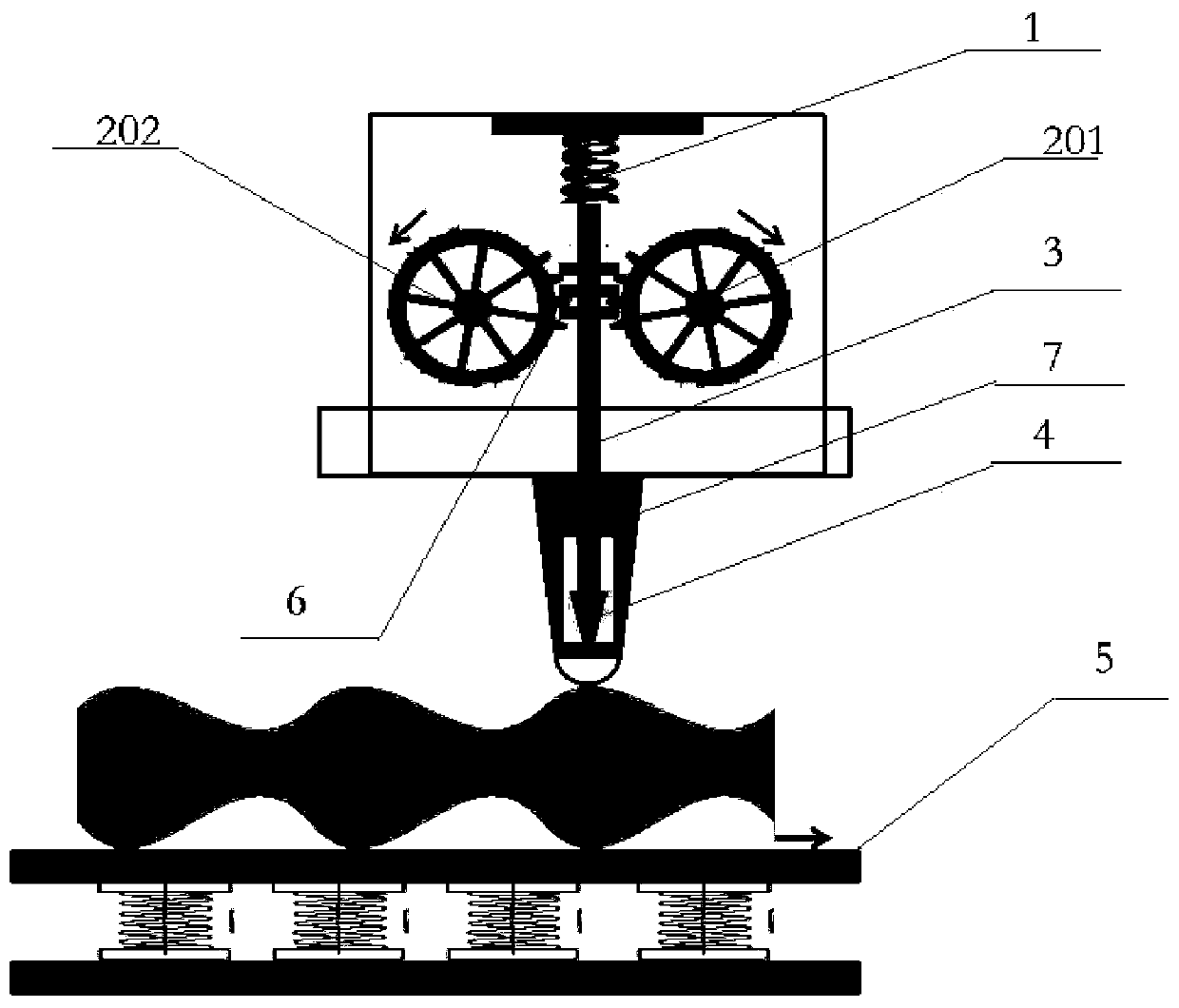
A cable metal shield stripping device
A technology of metal shielding layer and stripping device, which is applied in the direction of cable installation device, cable installation, dismantling/armored cable equipment, etc., can solve the problems of no way to recycle, uneven outer dimension of corrugated pipe, product recycling, etc., to achieve Effect of reducing stripping cost and improving stripping efficiency
- Summary
- Abstract
- Description
- Claims
- Application Information
AI Technical Summary
Problems solved by technology
Method used
Image

Examples
Embodiment Construction
[0024] The following will clearly and completely describe the technical solutions in the embodiments of the present invention with reference to the accompanying drawings in the embodiments of the present invention. Obviously, the described embodiments are only some, not all, embodiments of the present invention. Based on the embodiments of the present invention, all other embodiments obtained by persons of ordinary skill in the art without making creative efforts belong to the protection scope of the present invention.
[0025] The object of the present invention is to provide a cable metal shielding layer stripping device, which can avoid damage to the internal structure of the cable and increase the stripping speed when the metal shielding layer of the cable is stripped.
[0026] In order to make the above objects, features and advantages of the present invention more comprehensible, the present invention will be further described in detail below in conjunction with the accom...
PUM
 Abstract
Description
Claims
Application Information