Double-fed induction fan system based on coordinated control and low-voltage crossing method thereof

A doubly-fed induction fan, coordinated control technology, applied in the direction of control system, control generator, generator control circuit, etc., can solve the problems that can not fully meet the requirements of low voltage ride through, increase of DC voltage fluctuation, rotor surge current, etc. Achieve the effects of improving low-voltage ride-through capability, reducing torque oscillation, and reducing impedance value

Active Publication Date: 2019-03-15
SICHUAN UNIV
View PDF4 Cites 4 Cited by
  • Summary
  • Abstract
  • Description
  • Claims
  • Application Information

AI Technical Summary

Problems solved by technology

[0003] However, DFIG is sensitive to grid disturbances due to its direct connection to the grid at the stator end
The occurrence of severe voltage sags and the resulting stator flux response can cause significant electrical stress on the rotor-side converter and severe mechanical stress on mechanical components such as gearboxes
This low voltage operation also inhibits the full transmission of the power generated by the doubly-fed induction generator to the grid, which will lead to a large increase in the fluctuation of the DC voltage
In order for the doubly-fed induction generator to meet the low voltage ride-th

Method used


Image

  • Double-fed induction fan system based on coordinated control and low-voltage crossing method thereof
  • Double-fed induction fan system based on coordinated control and low-voltage crossing method thereof
  • Double-fed induction fan system based on coordinated control and low-voltage crossing method thereof

Examples


Embodiment Construction

[0026] The present invention will be further described in detail below in conjunction with test examples and specific embodiments. However, it should not be understood that the scope of the above subject matter of the present invention is limited to the following embodiments, and all technologies realized based on the content of the present invention belong to the scope of the present invention.

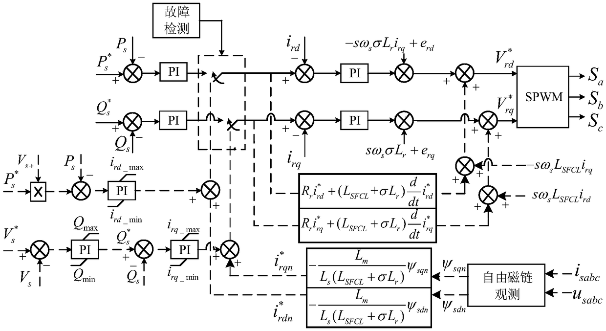
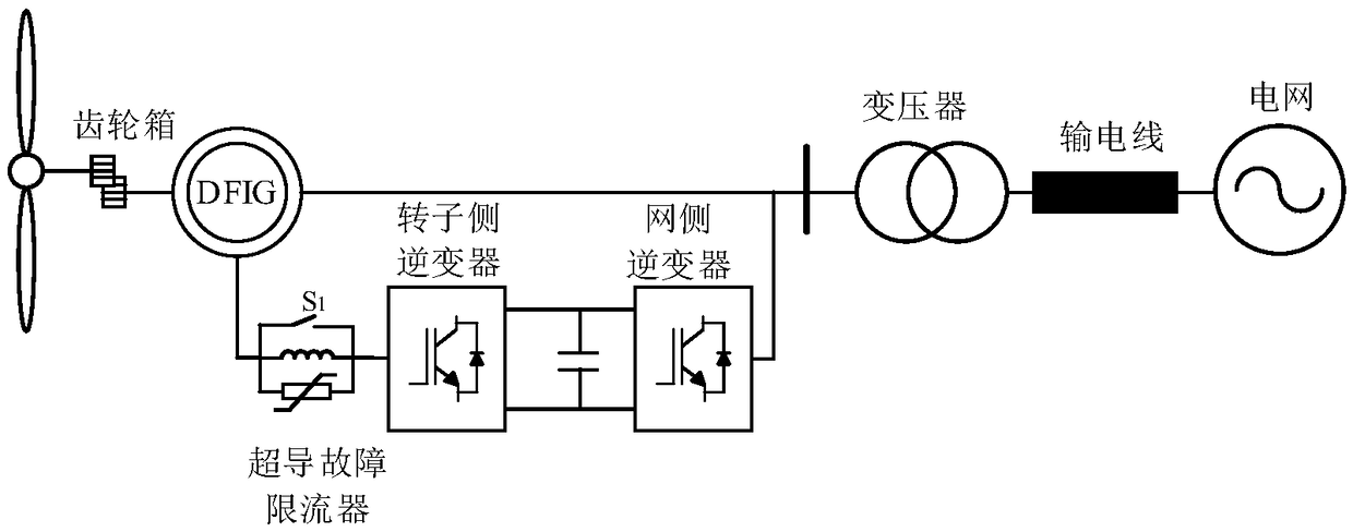
[0027] An embodiment of the present invention provides a coordinated control-based doubly-fed induction fan system (a doubly-fed induction fan system based on an inductive superconducting fault current limiter and current coordinated control). The doubly-fed induction fan system includes: a doubly-fed induction fan stator winding, a doubly-fed induction fan rotor, a rotor-side converter, and an inductive superconducting fault connected in series between the doubly-fed induction fan rotor and the rotor-side converter A current limiter; wherein, the inductive superconducting fault curr...


PUM


Abstract

The invention discloses a double-fed induction fan system based on coordinated control and a low-voltage crossing method thereof. The double-fed induction fan system is characterized by including a double-fed induction fan stator winding, a double-fed induction fan rotor, a rotor-side converter and an inductance type superconducting fault current limiter connected in series between the rotor and the rotor-side converter, wherein the fault current limiter comprises a superconducting coil and a power electronic switch which are connected in parallel. Through adoption of the inductance type superconducting fault current limiter and improvement of the control technology of the rotor-side convert of a double-fed induction fan, the superconducting fault current limiter is utilized to directly limit rotor overcurrent and reduce torque oscillation, and reactive power output of the double-fed induction motor is utilized during a fault period, thereby improving the low-voltage crossover capacityof the double-fed induction fan. At the same time, key parameter setting principles of the fault current limiter are determined by accurately controlling the current of the rotor-side converter during the fault period, so the impedance value of the superconducting fault current limiter is effectively reduced and the cost is saved.

Description

technical field [0001] The invention relates to the technical field of doubly-fed fan equipment, in particular to a doubly-fed induction fan system based on coordinated control and a low-voltage ride-through method thereof. Background technique [0002] Wind power generation is a power generation method with the largest installed capacity in new energy power generation. With the increasing penetration of wind power in the power system, the performance of wind turbines under grid faults is becoming more and more important for system stability. Common wind turbines include doubly-fed induction generators and permanent magnet direct drive generators. DFIG (double-fed induction fan) has the advantages of low cost, wide speed range, independent control of active and reactive power, etc. Due to its advantages for realizing grid integration, wind turbines based on doubly-fed induction generators are more commonly used in wind power generation. [0003] However, DFIG is sensitive...

Claims


Application Information

Patent Timeline
IPC IPC(8): H02J3/38H02P9/00H02H9/02H02P101/15
CPCH02H9/023H02J3/386H02P9/007H02P2101/15Y02E10/76Y02E40/60
Inventor 郑子萱肖先勇汪颖杜凯健李长松
Owner SICHUAN UNIV
Why Eureka
Try Eureka