Tunnel microwave communication transmission system and method

A microwave communication and transmission system technology, applied in wireless communication, electrical components, network planning, etc., to achieve the effect of reducing construction costs and maintenance costs

Active Publication Date: 2019-03-15
中科凯普(北京)导航通信技术有限公司
View PDF5 Cites 10 Cited by
  • Summary
  • Abstract
  • Description
  • Claims
  • Application Information

AI Technical Summary

Problems solved by technology

[0008] The object of the present invention is to solve the problem of microwave penetration / relay of communication network signals in tunnels, so that vehicles can provide common vehicles with , and even provide continuous, high-quality broadband mobile communication, network and multimedia services to passengers in high-speed trains

Method used


Image

  • Tunnel microwave communication transmission system and method
  • Tunnel microwave communication transmission system and method
  • Tunnel microwave communication transmission system and method

Examples


Embodiment 1

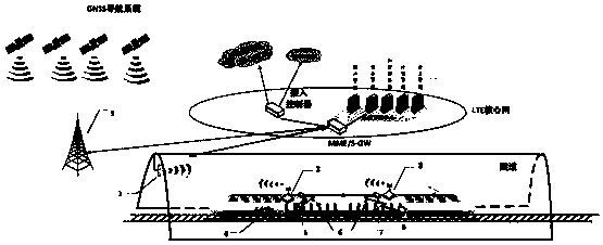
[0125] A tunnel with a length of 16km is a long straight tunnel. Next to the railway track at the entrance of the tunnel, a micro-base station antenna is erected with a ladder, with an antenna gain of 20dBi, a transmission power of 10W, and a height of 4 meters. The test terminal is mounted on the test vehicle, the antenna gain is 15dBi, the transmission power is 10 watts, and the antenna height is 2 meters. When the train does not enter the tunnel, the vehicle terminal antenna communicates with the LTE base station. The precise location information received by the navigation system combined with GNSS and inertial navigation is matched with the vehicle-specific electronic map, and the vehicle terminal system (VTS) control unit knows through calculation that the front antenna will enter the section of the tunnel after time t1 and continue driving in the tunnel 16km. The operating frequency of the system is 5.9GHz, and the tunnel section is circular arched, with a height of 9 ...

Embodiment 2

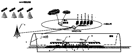
[0127] A long straight tunnel with a length of 55km. Next to the railway track at the entrance of the tunnel, a micro-base station antenna is erected with a ladder, with an antenna gain of 20dBi, a transmission power of 10W, and a height of 4 meters. The test terminal is mounted on the test vehicle, the antenna gain is 15dBi, and the antenna height is 2 meters. When the train does not enter the tunnel, the vehicle terminal antenna communicates with the LTE base station. The precise location information received by the navigation system combined with GNSS and inertial navigation is matched with the vehicle-specific electronic map. The vehicle terminal system (VTS) control unit knows through calculation that the front antenna will enter the section of the tunnel after time t2 and continue driving in the tunnel. 55km. The operating frequency of the system is 5.9GHz, and the tunnel section is circular arched, with a height of 9 meters and a width of 13.4 meters. It is calculate...

Embodiment 3

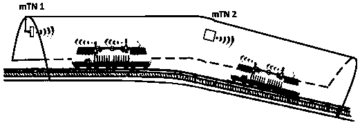
[0129] A curved tunnel with a length of 5456m. It starts as a linear tunnel with a length of 3,806 meters, followed by a curved tunnel with an arc length of 1,650 meters and a radius of 10,000 meters. In the middle of the tunnel entrance, a micro base station antenna is hung downwards, the antenna gain is 20dBi, the transmission power is 1W, and the antenna height is 7 meters; the test terminal is mounted on the test vehicle, the antenna gain is 15dBi, and the antenna height is 2 rice. When the train does not enter the tunnel, the vehicle terminal antenna communicates with the tunnel pico base station (mTN). The precise location information received by the navigation system combined with GNSS and inertial navigation is matched with the vehicle-specific electronic map, and the vehicle terminal system (VTS) control unit calculates that after time t3, the front antenna will enter the tunnel until the train exits tunnel to restore communication with the LTE base station. The op...


PUM


Abstract

The invention discloses a tunnel microwave communication transmission system and method. The tunnel micro base station system (1) comprises a supporting seat frame, an antenna, a radio remote unit, abaseband unit, a core network, a network server and a power supply. The tunnel micro base station system is used for, on one hand, interacting with MME / S-GW of a mobile communication exchange center to realize connection with an external network and on the other hand interacting with a vehicle-mounted terminal system so as to perform sending and receiving processing on a wireless interaction signal; the vehicle-mounted terminal system comprises an antenna base, an antenna cover, a GNSS antenna, a vehicle-mounted antenna, a vehicle-mounted frequency conversion module, a navigation system combined by GNSS and inertial navigation, a vehicle-mounted terminal device, an electronic map, a vehicle-mounted server, a power supply module and a control unit. The vehicle-mounted terminal system (2) isused for performing air interaction on the tunnel micro base station on one hand and providing a WI-FI service for users in cars of a train on the other hand. It is the first time to propose a mannerthat only a few tunnel micro base stations need to be set up in the tunnel to realize the communication in the tunnel; and a solution is proposed for communications in tunnels of complex types including curved tunnels, branched tunnels and the like.

Description

technical field [0001] The invention belongs to the field of mobile communication, in particular to a microwave penetration / relay system and communication transmission method for mobile communication network signals in a tunnel. Background technique [0002] In mobile communications, there are certain areas of weak field or "blind spots". For example, due to the shielding of tunnels, tall buildings or mountains, the field strength in the shadow area is extremely weak. Tunnels are often "blind spots" for radio wave propagation. Radio waves can propagate in a limited space, and the fading caused by multiple reflections and multipath effects on the tunnel wall is also obvious. Especially in the section close to the tunnel entrance, due to the coupling and discontinuity inside and outside the tunnel entrance, the transmission mode is complicated, and the deep fading of the field strength is more obvious. In addition, if the tunnel is curved, or there are obstacles on the prop...

Claims


Application Information

Patent Timeline
Patent Type & Authority Applications(China)
IPC IPC(8): H04W16/18H04W16/26
CPCH04W16/18H04W16/26
Inventor 崔君霞金声震庞峰胡超万庆涛王兆瑞高志勇李建斌
Owner 中科凯普(北京)导航通信技术有限公司
Why Eureka
Try Eureka