Dialysis device having a control unit for performing conditioning of the dialysis membrane

A technology of control unit and dialyzer, which is applied in the field of dialyzer, can solve the problems such as the difference in local filtration performance of the dialyzer membrane, and achieve the effects of improving blood compatibility, reducing sieving coefficient, and reducing loss

Active Publication Date: 2019-03-15
FRESENIUS MEDICAL CARE DEUTSCHLAND GMBH
View PDF6 Cites 0 Cited by
  • Summary
  • Abstract
  • Description
  • Claims
  • Application Information

AI Technical Summary

Problems solved by technology

However, the local filtration performance along the dialyzer membrane varies widely due to local transmembrane pressure (TMP) and local osmotic pressure variations

Method used


Image

  • Dialysis device having a control unit for performing conditioning of the dialysis membrane
  • Dialysis device having a control unit for performing conditioning of the dialysis membrane
  • Dialysis device having a control unit for performing conditioning of the dialysis membrane

Examples


example 1

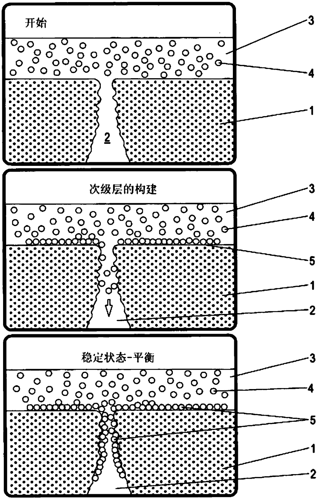
[0049] first according to Figure 5 Fabricate the experimental setup (step 1). The dialyzer 15 is filled and flushed with NaCl solution on the blood side and on the dialysate side, and residual air on both sides of the dialyzer 15 is completely removed by tapping (step 2). Subsequently, the blood side is filled with blood (step 3).

[0050] According to the invention, the blood pump 28 is then stopped (step 4) in order to reduce the pressure drop along the capillary of the dialyzer 15 .

[0051] About 1 / 3 of the volume on the blood side is drawn through the membrane by means of the displacement pump 29 (step 5). ΔV uf The value is 30ml. Therefore, the ultrafiltration volume ΔV uf is drawn evenly through the membrane. The process is carried out as follows: Instead of pump 29 on the dialysate side with Q uf = 60ml / min to draw until the desired ultrafiltration (UF) volume of 30ml is drawn for each cycle (for about 30s to 60s). Blood pump 28 operates at half UF rate during...

example 2

[0060] This example is mostly the same as Example 1, but the conditioning cycle, steps 5 to 8, is repeated a total of 15 times, that is, the total V in the conditioning cycle uf is 450mL, the process of step 5 is as follows: replace the pump 29 on the dialysate side with Q uf = 90ml / min to draw until the desired ultrafiltration (UF) volume of 30ml is drawn for each cycle of 30ml (duration approximately 30s to 60s). Blood pump 28 operates at half UF rate during this phase, where Q b = 45ml / min. The residual volume flow (approximately 45 ml / min) is recovered via the venous hose system 19 .

[0061] Evaluation was performed as in Example 1.

[0062] According to slightly changed example 2', it is also possible to consider setting Qb to 40ml / min, which is at the rate of Q uf = 90ml / min would result in a reflux rate of 50ml / min from the venous line.

example 3

[0064] This example is also mostly the same as example 1, but here, in step 5, with the conditioning cycle of steps 5 to 8 carried out 5 times, ie 225 m, the volume on the blood side is drawn via the membrane with a syringe or instead of a pump 29 About 1 / 2 of , ie ΔV uf = 45ml.

[0065] The evaluation was performed again as in Example 1.


PUM


Abstract

The invention relates to a dialysis device, comprising an extracorporeal blood circuit, a dialyzer, and a dialysate circuit, wherein a blood pump is arranged in the extracorporeal blood circuit, wherein the dialyzer has a dialysis membrane, which separates the blood side of the dialyzer from the dialysate side of the dialyzer, wherein the dialysis device has a control unit, which is designed to perform a conditioning cycle, which comprises a conditioning phase, in which an ultrafiltration rate exceeds the blood flow through the dialyzer, which blood flow is conveyed by the blood pump.

Description

technical field [0001] The invention relates to a dialyzer having an extracorporeal blood circuit, a dialyzer and a dialysate circuit, wherein a blood pump is arranged in the extracorporeal blood circuit. Background technique [0002] For starting a dialysis treatment, such as a hemodialysis treatment or a hemodiafiltration treatment, the dialyzer exhibits a very high permeability to larger molecules, especially albumin. By contact with specific blood components, especially blood proteins, the dialysis membrane is modified such that the filtration of large proteins such as albumin is greatly improved. In detail, due to the pooling of albumin and other blood constituents on the dialysis membrane, a secondary membrane is formed which leads to a desirably better sieving of large proteins such as albumin. The change process is schematically shown in figure 1 , where the upper figure shows the membrane 1 with the membrane pores 2 at the beginning of the treatment. In the early...

Claims


Application Information

Patent Timeline
IPC IPC(8): A61M1/16A61M1/36
CPCA61M2202/0057A61M2202/0445A61M1/1676A61M1/365A61M1/1601
Inventor 赖纳·施皮克曼阿尔弗雷德·加格尔
Owner FRESENIUS MEDICAL CARE DEUTSCHLAND GMBH
Why Eureka
Try Eureka