Method for manufacturing optical member

A technology of optical components and manufacturing methods, applied in chemical instruments and methods, lamination auxiliary operations, lamination, etc., can solve the problems of low anti-fouling, difficult to wipe fingerprints, etc., to improve anti-fouling and abrasion resistance Effect

Active Publication Date: 2019-03-15
SHARP KK
View PDF7 Cites 0 Cited by
  • Summary
  • Abstract
  • Description
  • Claims
  • Application Information

AI Technical Summary

Problems solved by technology

However, in conventional optical members, since the surface has a concave-convex structure, there is a problem that it is difficult to wipe off fingerprints, that is, the antifouling property is low.

Method used


Image

  • Method for manufacturing optical member
  • Method for manufacturing optical member
  • Method for manufacturing optical member

Examples


Embodiment approach 1

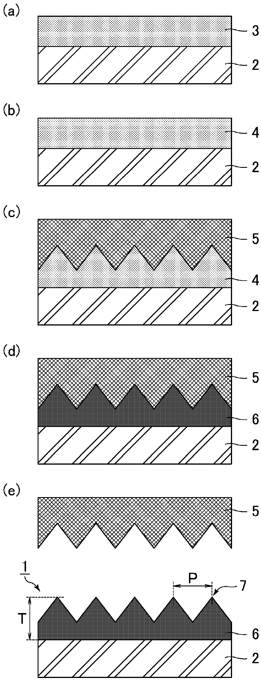
[0032] The manufacturing method of the optical member of Embodiment 1 relates to the manufacturing method of the 1st optical member of this invention. Refer to the following figure 1 The manufacturing method of the optical member of Embodiment 1 is demonstrated. figure 1 It is a cross-sectional schematic diagram for demonstrating the manufacturing method of the optical member of Embodiment 1.

[0033] (Process (1): Preparation of resin solution)

[0034] A photocurable resin and a release agent are dissolved in a solvent to prepare a resin solution 3 .

[0035] The preparation of the resin solution 3 is performed in the following procedure, for example.

[0036] (i) Various monomers, photopolymerization initiators, etc. are mixed appropriately to prepare a photocurable resin (transparent state).

[0037] (ii) A mixture of a photocurable resin and a release agent is prepared (cloudy state).

[0038] (iii) A mixture of a photocurable resin and a release agent is dissolved...

Embodiment approach 2

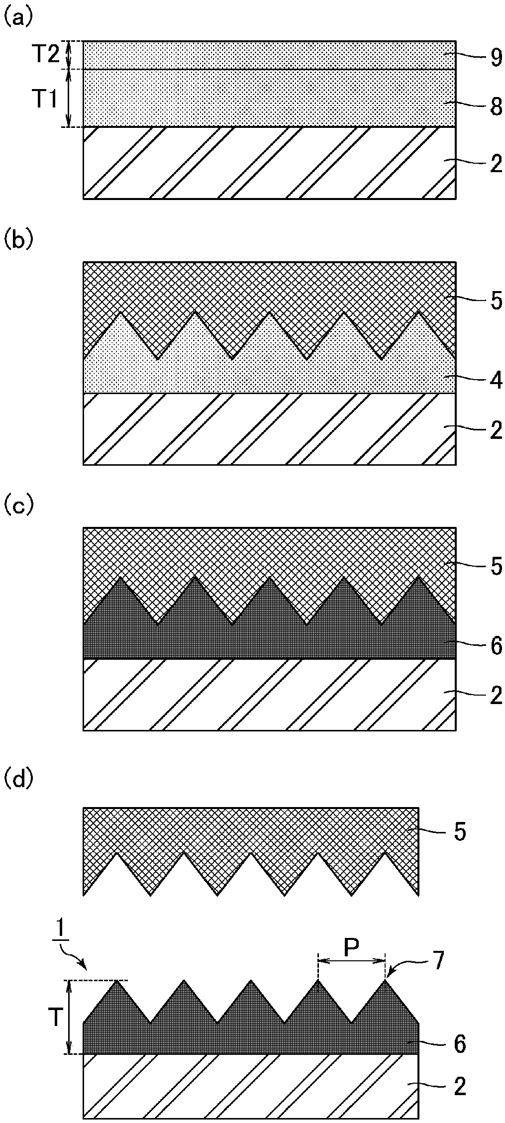
[0101] The manufacturing method of the optical member of Embodiment 2 relates to the manufacturing method of the 2nd optical member of this invention. Refer below figure 2 The manufacturing method of the optical member of Embodiment 2 is demonstrated. figure 2 It is a cross-sectional schematic diagram for demonstrating the manufacturing method of the optical member of Embodiment 2. The manufacturing method of the optical member of Embodiment 2 is the same as the manufacturing method of the optical member of Embodiment 1, except that the photocurable resin and the release agent are divided into two layers and applied, and then the two layers are integrated. , so descriptions are appropriately omitted for the repetitions.

[0102] (Process (1): Application of the first resin and the second resin)

[0103] Such as figure 2 As shown in (a), the first resin 8 containing a photocurable resin is applied to the surface of the substrate 2 . Next, the second resin 9 containing a...

Embodiment approach 3

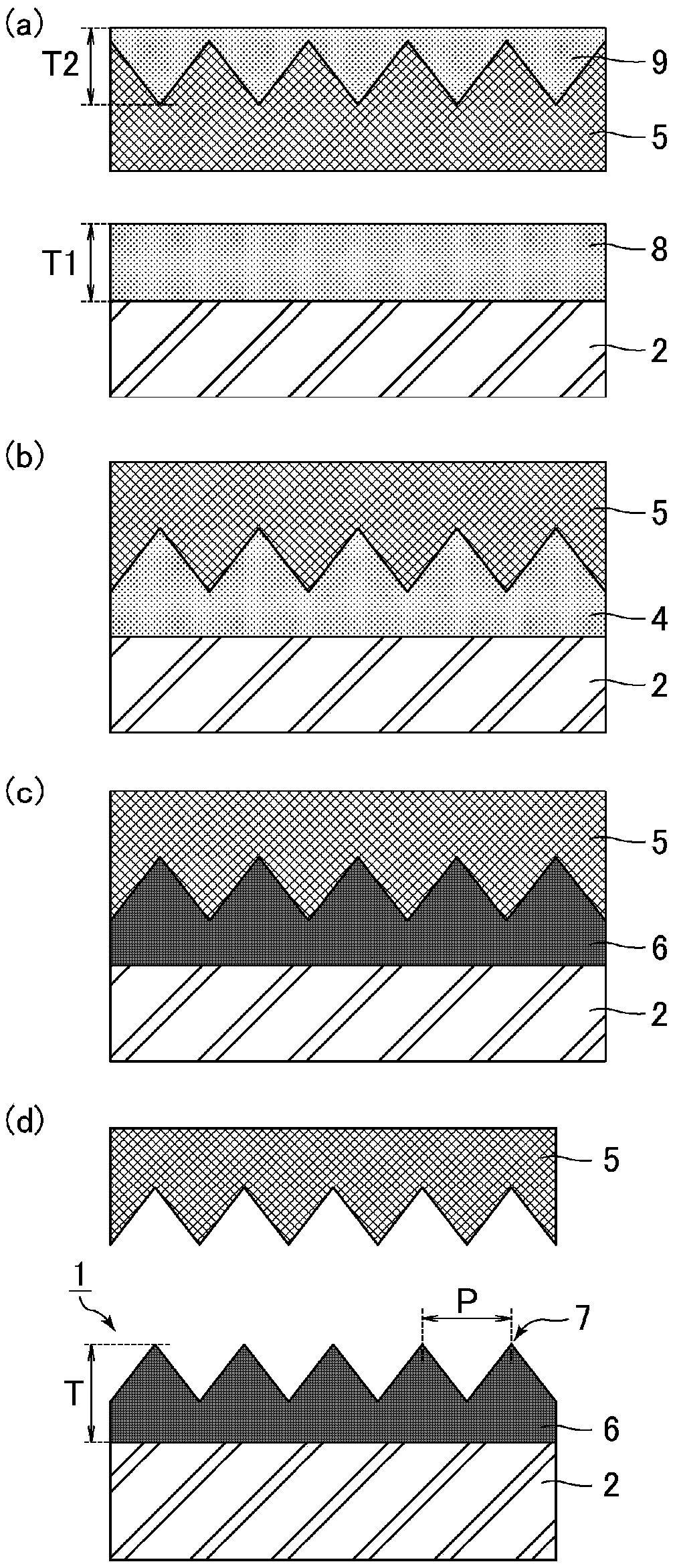
[0124] The manufacturing method of the optical member of Embodiment 3 relates to the manufacturing method of the 2nd optical member of this invention. Refer below image 3 The manufacturing method of the optical member of Embodiment 3 is demonstrated. image 3 It is a cross-sectional schematic diagram for demonstrating the manufacturing method of the optical member of Embodiment 3. The manufacturing method of the optical member in Embodiment 3 is the same as the manufacturing method of the optical member in Embodiment 2 except that the second resin is applied to the surface of the mold. Therefore, descriptions of overlapping parts are appropriately omitted.

[0125] (Process (1): Application of the first resin and the second resin)

[0126] Such as image 3 As shown in (a), the first resin 8 containing a photocurable resin is applied to the surface of the substrate 2 . Next, the second resin 9 containing a release agent is applied to the surface (concave-convex surface) of...


PUM

PropertyMeasurementUnit
thicknessaaaaaaaaaa
heightaaaaaaaaaa
thicknessaaaaaaaaaa

Abstract

The present invention provides a method for manufacturing an optical member, whereby antifouling properties and abrasion resistance are increased without compromising transparency. This method for manufacturing an optical member is a method for manufacturing an optical member provided with a substrate and a polymer layer having an uneven structure on a surface thereof in which a plurality of projections are provided at a pitch equal to or less than the wavelength of visible light, wherein the method includes a process (1) for dissolving a photocurable resin and a release agent in a solvent andpreparing a resin solution, a process (2) for applying the resin solution to the surface of the substrate, a process (3) for performing a heat treatment for removing the solvent from the applied resin solution and forming a resin layer, a process (4) for pressing the substrate against a die in a state in which the resin layer is sandwiched between the die and the substrate and forming the unevenstructure on the surface of the resin layer, and a process (5) for curing the resin layer by photoirradiation and forming the polymer layer, the photocurable resin and the release agent being a combination exhibiting a predetermined turbidity when mixed with each other, and the optical member having a haze of less than 1.0%.

Description

technical field [0001] This invention relates to the manufacturing method of an optical member. More specifically, it relates to a method of manufacturing an optical member having a nano-sized uneven structure. Background technique [0002] Applications of optical members to various fields have been studied (for example, refer to Patent Documents 1 to 5). In particular, an optical member having a nano-sized concave-convex structure (nanostructure) is known to have excellent antireflection properties. According to such a concavo-convex structure, the refractive index changes continuously from the air layer to the substrate, so reflected light can be drastically reduced. [0003] prior art literature [0004] patent documents [0005] Patent Document 1: JP-A-2007-178724 [0006] Patent Document 2: JP-A-2005-97371 [0007] Patent Document 3: International Publication No. 2015 / 060458 [0008] Patent Document 4: International Publication No. 2013 / 187506 [0009] Patent...

Claims


Application Information

Patent Timeline
Patent Type & Authority Applications(China)
IPC IPC(8): B29C59/02B32B3/30B32B38/06
CPCB29C59/02B32B3/30B32B38/06
Inventor 厚母贤芝井康博中松健一郎
Owner SHARP KK
Why Eureka
Try Eureka