Bending machine

A bending machine and combined technology, applied in the field of bending machines, can solve the problems of poor bending effect, high cost, and low efficiency, and achieve the effects of low manufacturing cost, simple structure, and improved work efficiency

Inactive Publication Date: 2019-03-19
KUNMING UNIV OF SCI & TECH
View PDF9 Cites 2 Cited by
  • Summary
  • Abstract
  • Description
  • Claims
  • Application Information

AI Technical Summary

Problems solved by technology

[0003] The technical problem to be solved by the present invention is: the present invention provides a bending machine to solve the problems of poor bending effect, low efficiency and high cost in the prior art

Method used


Image

  • Bending machine
  • Bending machine
  • Bending machine

Examples


Embodiment 1

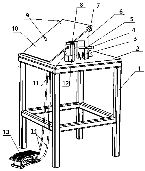
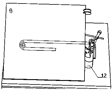
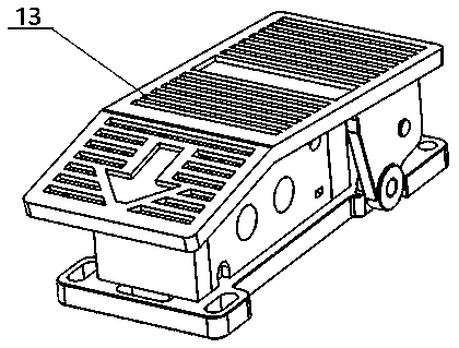
[0027] Embodiment 1: as Figure 1-10 As shown, a bending machine includes a frame 1, an upper panel 2, a cylinder support plate 3, a handle 4, a cylinder 5, a vertical plate 6, a bending wheel 7, a pin 8, a positioning pin 9, a bottom plate 10, and a Wheel 11, turning block 12, foot switch 13, air pipe 14, deformation wheel 15;

[0028] Described frame 1 is welded together with upper panel 2, and cylinder support plate 3 and vertical plate 6 are vertically welded on upper panel 2 respectively, to support cylinder 5 and base plate 10, and base plate 10 forms certain angle with upper panel 2, and one end It is welded with the upper panel 2, and the other end is welded with the vertical plate 6. The roller 11 and the rotary block 12 are connected with the upper panel 2 through screws, and the roller 11 is stepped, and the upper half is 2 / of the shaft diameter. 3 and has an arc-shaped groove, wherein the roller 11 is fixed relative to the upper panel 2, and the two bosses of the...


PUM


Abstract

The invention relates to a bending machine and belongs to the technical field of bending equipment. The bending machine comprises a rack, an upper panel, an air cylinder supporting plate, a handle, anair cylinder, a vertical plate, a bending wheel, a pin, positioning pins, a bottom plate, a leaning wheel, a rotating block, a step switch, air pipes and a deformation wheel. The rack is welded to the upper panel. The air cylinder supporting plate and the vertical plate are welded to the upper panel. A certain angle is formed between the bottom plate and the upper panel, and the bottom plate andthe upper panel are welded to the vertical plate. The bending wheel and the positioning pins are welded to the bottom plate. The leaning wheel is connected with the upper panel through a screw. The deformation wheel is connected with the rotating block through the pin. The air cylinder is connected with the handle through a nut so as to transmit powder. The handle is welded to the rotating block.The step switch is connected with the air cylinder and an externally-connected air pump through the air pipes. An air cylinder piston rod is controlled to move through pressing of the step switch. Thebending machine is simple in structure and low in manufacturing cost, pneumatic back bending is used for replacing traditional manual back bending, physical force is saved, and the work efficiency isimproved.

Description

technical field [0001] The invention relates to a bending machine, which belongs to the technical field of bending equipment. Background technique [0002] With the development of science and technology and the improvement of the quality of life, devices such as evaporators are more and more widely used in people's lives. Evaporators are mainly divided into aluminum tube evaporators and copper tube evaporators according to different materials. In order to make the evaporator have better heat dissipation, the evaporator generally needs to be bent and formed multiple times. At present, most of the bending machines on the market are special bending machines for a certain product, and there are few automatic bending machines. In actual production, the bending of finned evaporators still uses traditional manual bending, which seriously reduces the Increased production efficiency and increased production costs. Contents of the invention [0003] The technical problem to be sol...

Claims


Application Information

Patent Timeline
Patent Type & Authority Applications(China)
IPC IPC(8): B21D53/06B21D7/024
Inventor 李金乐李珊杨晓京马一鸣张天欢张逸飞
Owner KUNMING UNIV OF SCI & TECH
Why Eureka
Try Eureka