
Generating method cycloid tooth bevel gear grinding method

A cycloid bevel gear, forming technology, applied in the direction of components with teeth, belts/chains/gears, gear teeth, etc., can solve the problem that the processing efficiency cannot adapt to the finishing of large quantities of small and medium-sized gears.

Active Publication Date: 2019-03-19
CHONGQING UNIV OF TECH
View PDF9 Cites 6 Cited by
  • Summary
  • Abstract
  • Description
  • Claims
  • Application Information

AI Technical Summary

Problems solved by technology

After using these methods to replace the milling tool with a grinding wheel of the corresponding shape, although it can also be used for the grinding of cycloidal bevel gears, its processing efficiency cannot adapt to the finishing of large batches of small and medium-sized gears

Method used

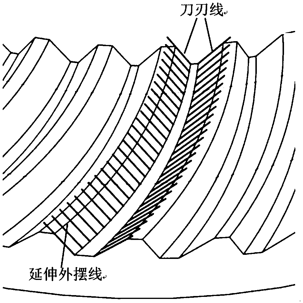
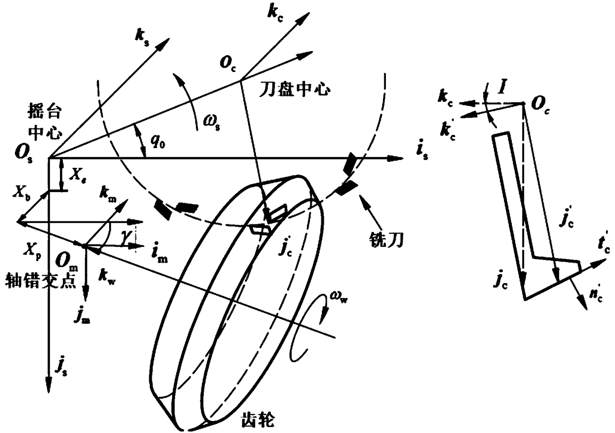
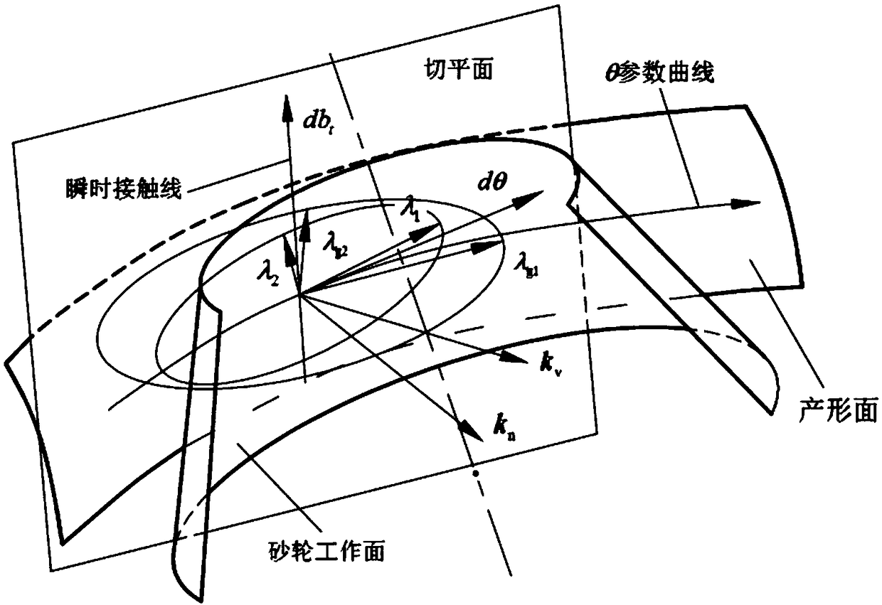

Image

  • Generating method cycloid tooth bevel gear grinding method
  • Generating method cycloid tooth bevel gear grinding method
  • Generating method cycloid tooth bevel gear grinding method

Examples


Embodiment 1

[0052] Embodiment one, a kind of tooth grinding method of forming method cycloid bevel gear, it comprises the following steps:

[0053] Step 1, the cycloidal bevel gear is processed by forming face hobbing method, see figure 2 The mathematical model of the face hobbing process shown by the forming method is used to establish a cycloidal bevel gear processing coordinate system group; the cradle coordinate system ∑ s ={O s , i s , j s , k s}, O s is the center of the cradle, i s o s j s is the plane of the cradle, k s The axis of the cradle points to the inside of the cradle; the cutterhead coordinate system Σ c ={O c , i c , j c , k c}, O c is the center of the cutterhead, i c o c j c on the top plane of the knife, j c is the direction from the center of the cutter head to the reference point of the cutting tooth on the cutting edge, k c The axis of the cutter head deviates from the plane of the top of the cutter; the gear coordinate system ∑ g ={O g , i ...

Embodiment 2

[0105] Example 2: Cycloidal bevel gears are manufactured by molding method, the basic parameters of which are shown in Table 1, and the machine tool adjustment parameters and cutter head parameters are shown in Table 2.

[0106] Table 1 Basic parameters of cycloidal bevel gears

[0107]

[0108] Table 2 Machine tool adjustment parameters and cutterhead parameters

[0109]

[0110] Using the surface equation of the cycloidal bevel gear, the parameters of the grinding wheel required for gear grinding can be designed, and the interference-free analysis and adjustment of the grinding wheel can be ensured. Depend on and Calculation, select the Δ value appropriately, and determine the pressure angle of the working face of the grinding wheel for gear grinding as The reference point radius is R g =77.2, grinding the convex surface of the cycloidal bevel gear with the grinding wheel on the inner side as the working surface. The tool position point calculated by the tool pos...


PUM


Abstract

The invention discloses a generating method cycloid tooth bevel gear grinding method. The generating method cycloid tooth bevel gear grinding method comprises the following steps: first, a machining coordinate system set of a generating method cycloid tooth bevel gear is established; second, the tooth surface equation of a generating wheel is determined, and the generating wheel tooth surface of the generating method cycloid tooth bevel gear is the gear tooth surface; third; grinding wheel parameters for gear grinding are determined; fourth, interference analysis and correction calculation areconducted; and fifth, the gear grinding tool position is calculated. According to the generating method cycloid tooth bevel gear grinding method, a grinding wheel structure of gear grinding and geargrinding moving parameters are determined according to a tooth surface machining mathematical model and parameter calculation, one tooth surface is ground in one-time gear grinding movement by adopting a large-diameter conical surface grinding wheel, and thus the precision and the efficiency are high.

Description

technical field [0001] The invention relates to gear machinery manufacturing, in particular to a method for grinding cycloidal bevel gears by forming method. Background technique [0002] Spiral bevel gears are used for motion and power transmission of two intersecting or intersecting axes in space. It has the advantages of strong bearing capacity, stable transmission, low noise, long service life, compact structure, high working reliability, etc. It is widely used in the power transmission structure of automobiles, aircrafts, heavy machinery and other machines. [0003] The processing of spiral bevel gears is divided into two types: end milling method and end hobbing method. The spiral bevel gears processed by the two methods are called arc bevel gears and cycloid bevel gears respectively. The face hobbing method is very efficient because it can use a cutterhead to perform continuous tooth-dividing motion to complete the machining of both sides of the gear in one installat...

Claims


Application Information

Patent Timeline
Patent Type & Authority Applications(China)
IPC IPC(8): B23F1/02
CPCB23F1/02
Inventor 张卫青郭晓东张明德谭儒龙郑方焱
Owner CHONGQING UNIV OF TECH
Learn More