
Blast furnace gas and main air pipe communicating system

A blast furnace gas and main air pipe technology, applied in blast furnaces, blast furnace details, blast furnace parts, etc., can solve problems such as smooth production, energy saving and consumption reduction, avoid waste heat recovery and unstable heating in steelmaking, and ensure safety , Improve the effect of equipment utilization

Pending Publication Date: 2019-03-19
云南玉溪仙福钢铁(集团)有限公司
View PDF12 Cites 4 Cited by
  • Summary
  • Abstract
  • Description
  • Claims
  • Application Information

AI Technical Summary

Problems solved by technology

[0003] The purpose of the present invention is to provide a network system for blast furnace gas and main air pipes, which solves the problem that when a certain blast furnace is shut down or the wind is slow, the turbine has to be unloaded off-line due to no gas supply, which is beneficial to the smooth production and energy saving. problems affecting

Method used


Image

  • Blast furnace gas and main air pipe communicating system

Examples


Embodiment 1

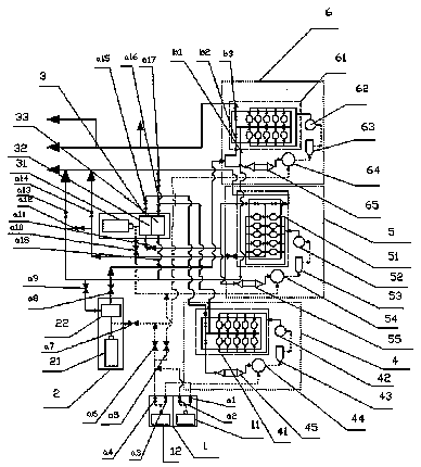
[0023] Such as figure 1 The shown blast furnace gas and main air duct network system includes a fan system, a blast furnace system and a control valve. The fan system is connected to the blast furnace system through a pipeline, and a control valve is arranged on the pipeline. The fan system and the blast furnace system are respectively set as 3, the fan systems are respectively the first fan system 1, the second fan system 2 and the third fan system 3, the blast furnace systems are respectively the first blast furnace system 4, the second blast furnace system 5 and the third blast furnace system 6, the first blast furnace system The first fan system 1, the second fan system 2 and the third fan system 3 are connected to each other;

[0024] In this embodiment, by connecting the three fan systems, when a problem occurs in one of them, another fan can work instead.

Embodiment 2

[0026] On the basis of the above-mentioned embodiments, in this embodiment, in order to prevent the two fans from working continuously for a long time, causing the pipeline to depressurize, the first fan system 1 is provided with a first main fan 11 and a backup fan 12. The air outlet of the air outlet is communicated with the standby blower fan 12 by the air duct, and the extra partial pressure is provided by setting the standby blower blower.

Embodiment 3

[0028] On the basis of the above-mentioned embodiments, in this embodiment, in order to use the kinetic energy of the fan to provide the power for gas transportation, the second fan system 2 is provided with a second fan 21, and the rear end of the second fan 21 is connected to a second fan through an air duct. A turbine 22, the turbine 22 is provided with a gas pipeline connected to the blast furnace system. The turbine 22 is driven to work by the second fan 21 so as to transport the gas into the pipeline system.


PUM


Abstract

The invention discloses a blast furnace gas and main air pipe communicating system. The blast furnace gas and main air pipe communicating system comprises fan systems, blast furnace systems and control valves, wherein the fan systems communicate with the blast furnace systems through pipelines, the control valves are arranged on the pipelines, the number of the fan systems and the number of the blast furnace systems are three correspondingly, the fan systems comprise the first fan system, the second fan system and the third fan system, the blast furnace systems comprises the first blast furnace system, the second blast furnace system and the third blast furnace system, and the first fan system, the second fan system and the third fan system communicate with one another. Thus, the problem that when blowing-down or slow-air blowing occurs to a certain blast furnace, a turbine motor has to be shut down and dismounted due to the fact that no gas is supplied, and then influence is generatedon production, energy conservation and consumption reduction is solved, then all air pipes communicate with one another, and interchange is realized.

Description

technical field [0001] The invention relates to the technical field of waste heat recovery and utilization in iron and steel enterprises, in particular to a blast furnace gas and main air pipe network communication system. Background technique [0002] In the iron and steel smelting industry, a large amount of wind and clean gas are usually blown into the smelting blast furnace. However, in production practice, due to the individual design of the blast furnace, the fans of each blast furnace cannot be interchanged for backup, so that when the main fan system of a certain blast furnace fails At the same time, when a blast furnace is shut down or the wind is slow, the turbine has to be off-line and unloaded due to no gas supply, which has a great impact on the smooth production and energy saving. Contents of the invention [0003] The purpose of the present invention is to provide a network system for blast furnace gas and main air pipes, which solves the problem that when a...

Claims


Application Information

Patent Timeline
Patent Type & Authority Applications(China)
IPC IPC(8): C21B5/06C21B7/00C21B9/10C21B7/22
CPCC21B5/06C21B7/002C21B7/22C21B9/10
Inventor 李凤宝黄发文李学新
Owner 云南玉溪仙福钢铁(集团)有限公司
Learn More