
Advanced heat insulation compressed air energy storage system with electric heating heat preservation sleeves

A compressed air energy storage and electric heating technology, which is applied to lighting and heating equipment, heat storage equipment, indirect heat exchangers, etc., can solve the problems of low work efficiency, increase the air flow in the energy release stage, and less work, and achieve Increased air flow, extended working time, and improved working ability

Inactive Publication Date: 2019-03-19
CHONGQING UNIV
View PDF4 Cites 9 Cited by
  • Summary
  • Abstract
  • Description
  • Claims
  • Application Information

AI Technical Summary

Problems solved by technology

[0006] In view of the above-mentioned deficiencies existing in the prior art, the purpose of the present invention is to solve the problems of the existing CAES technology turbines with small working capacity, small work per unit time, and low work efficiency, and provide an advanced heat-insulating sleeve with an electric heating insulation sleeve. The compressed air energy storage system (AA-CAES) can use the electric power when the electricity is surplus to heat the electric thermal insulation sleeve to make its temperature higher than the gas temperature at the inlet of the expander; and heat the gas at the inlet of the expander through the high temperature sleeve , so that the working capacity of the expander is improved, and the air flow in the energy release stage can also be increased to increase the output power of the turbine; thereby greatly improving the working efficiency and output power of the AA-CAES system

Method used


Image

  • Advanced heat insulation compressed air energy storage system with electric heating heat preservation sleeves

Examples


Embodiment

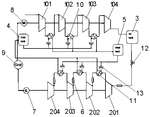
[0021] Example: see figure 1 , an advanced adiabatic compressed air energy storage system with electric heating insulation sleeve, including compressor unit, expansion unit, compressed air storage tank 3, cold storage tank 4, heat storage tank 5, electric heating insulation sleeve 6, power generation Machine 7, motor 8 and external grid 9. Wherein, the compressor unit includes a first-stage compressor 101, a second-stage compressor 102, a third-stage compressor 103, and a fourth-stage compressor 104 arranged coaxially and connected in sequence. The couplings are adjacent; the expansion unit includes a first-stage expander 201, a second-stage expander 202, a third-stage expander 203, and a fourth-stage expander 204, which are arranged coaxially and connected in sequence. The drive shaft and coupling are adjacent; the compressors at all stages are turbocompressors, and the expanders at all stages are turboexpanders. Wherein, the gas outlet of the four-stage compressor 104 is c...


PUM


Abstract

The invention discloses an advanced heat insulation compressed air energy storage system with electric heating heat preservation sleeves. The advanced heat insulation compressed air energy storage system comprises a compressor unit, an expansion machine unit, a compressed air storage tank, a cold storage tank, a heat storage tank, the electric heating heat preservation sleeves, a power generator,a motor and an external power grid; and the compressor unit is connected to the compressed air storage tank, the compressed air storage tank is connected to the expansion machine unit, a first heat exchanger is arranged between every two adjacent stages of compressors, a second heat exchanger is arranged between every two adjacent stages of expanding machines, a pipe between the compressed air storage tank and the first-stage expansion machine and a pipe between the second heat exchanger and the later-stage expansion machine are sleeved with the electric heating heat preservation sleeves, andthe electric heating heat preservation sleeves are connected with the external power grid. According to the advanced heat insulation compressed air energy storage system, the power capability of the expansion machines can be improved, the air flow in the energy release stage can be increased to increase the turbine output power, and the acting efficiency and the output power of an AA-CAES system are greatly improved.

Description

technical field [0001] The invention relates to the field of advanced adiabatic compressed air energy storage, in particular to an advanced adiabatic compressed air energy storage system (AA-CAES) with an electric heating insulation sleeve. Background technique [0002] Among the existing energy storage technologies, compressed air energy storage is favored by people for its advantages of large energy storage scale, long storage period, and less environmental pollution. With the development of renewable energy, it is imperative to develop large-scale energy storage, which has broad application prospects. [0003] my country's research and development of compressed air energy storage systems started relatively late, but with the rapid increase in demand for electric energy storage, related research has gradually been valued by some universities and scientific research institutions. At present, there is no traditional compressed air energy storage power station in commercial ...

Claims


Application Information

Patent Timeline
IPC IPC(8): F04B41/02F04B41/06F04B35/04F01D15/10F01D13/00F02C1/00F28D20/00
CPCF01D13/00F01D15/10F02C1/00F04B35/04F04B41/02F04B41/06F28D20/00F28D2020/0004Y02E60/14Y02E60/16
Inventor 杨晨李盼孙溧邓康杰张涛刘思遥姚凯范远哲
Owner CHONGQING UNIV
Learn More