Gas turbine combustion chamber swirler and assembly

A gas turbine and swirler technology, applied in the combustion chamber, continuous combustion chamber, combustion method, etc., can solve the problems of smaller load adjustment range, poor combustion stability, combustion oscillation, etc., to prevent backfire, stable airflow, and stable burning effect

Inactive Publication Date: 2019-03-19
DONGFANG TURBINE CO LTD
View PDF6 Cites 4 Cited by
  • Summary
  • Abstract
  • Description
  • Claims
  • Application Information

AI Technical Summary

Problems solved by technology

But at the same time, due to the transformation of the combustion mode, it also brings a series of challenges to the design of

Method used


Image

  • Gas turbine combustion chamber swirler and assembly
  • Gas turbine combustion chamber swirler and assembly
  • Gas turbine combustion chamber swirler and assembly

Examples


Embodiment 1

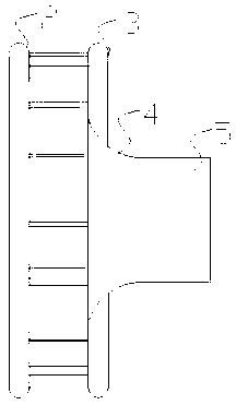
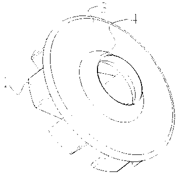
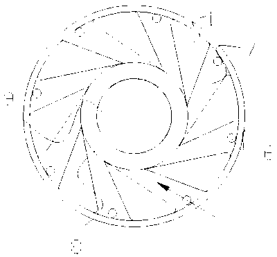
[0032] Such as figure 1 As shown in -4, a gas turbine combustor swirler and assembly of the present embodiment includes a swirler and a guide ring 4 and a premixing chamber 5 arranged downstream of the swirler air flow, and the guide ring 4 is located in the swirl Between the swirler and the premixing chamber 5, the swirler, the guide ring 4 and the premixing chamber 5 are integrally formed; the swirler is a radial swirler, including a plurality of swirl blades 1 arranged in a circle, and the swirl The top of the flow blade 1 is fixedly connected with the circular end plate 3, the bottom of the swirl blade 1 is connected with the burner end cover 2 by bolts, the burner end cover 2 is provided with a fuel nozzle assembly hole, and the burner end cover 2 and the circular end The plates 3 are set concentrically, and the circular end plate 3 is provided with a concentric center hole; the swirl blades 1 extend radially, and a swirl channel 7 extending along the direction of the ce...

Embodiment 2

[0035] Such as figure 1 -2 and Figure 5-6 As shown, a gas turbine combustor swirler and assembly of the present embodiment includes a swirler and a guide ring 4 and a premixing chamber 5 arranged downstream of the swirler air flow, and the guide ring 4 is located between the swirler and the swirler. Between the premixing chambers 5, swirlers, guide rings 4 and premixing chambers 5 are integrally formed; the swirlers are radial swirlers, including a plurality of swirl vanes 1 arranged in a circle, and the swirl vanes 1 The top is fixedly connected with the circular end plate 3, the bottom of the swirl vane 1 is bolted to the burner end cover 2, the burner end cover 2 is provided with a fuel nozzle assembly hole, the burner end cover 2 and the circular end plate 3 Set concentrically, the circular end plate 3 is provided with a concentric center hole; the swirl blades 1 extend in the radial direction, and a swirl channel 7 extending along the direction of the center hole is fo...

Embodiment 3

[0038] Such as figure 1 As shown in -4, a gas turbine combustor swirler and assembly of the present embodiment includes a swirler and a guide ring 4 and a premixing chamber 5 arranged downstream of the swirler air flow, and the guide ring 4 is located in the swirl Between the swirler and the premixing chamber 5, the swirler, the guide ring 4 and the premixing chamber 5 are integrally formed; the swirler is a radial swirler, including a plurality of swirl blades 1 arranged in a circle, and the swirl The top of the flow blade 1 is fixedly connected with the circular end plate 3, the bottom of the swirl blade 1 is connected with the burner end cover 2 by bolts, the burner end cover 2 is provided with a fuel nozzle assembly hole, and the burner end cover 2 and the circular end The plates 3 are set concentrically, and the circular end plate 3 is provided with a concentric center hole; the swirl blades 1 extend radially, and a swirl channel 7 extending along the direction of the ce...


PUM


Abstract

The invention belongs to the technical field of gas turbines, and discloses a gas turbine combustion chamber swirler and assembly which comprises a swirler, a flow guiding ring and a premixing cavity.The swirler communicates with the flow guiding ring which communicates with the premixing cavity; the swirler is a radial swirler and comprises a plurality of swirling blades which are distributed ina circle, the bottoms of the swirling blades are connected with a combustor end cover through bolts, the tops of the swirling blades are fixedly connected with a circular end plate, the combustor endcover and the circular end plate are concentrically arranged, and the circular end plate is provided with a concentric central hole; the swirling blades extend in the radial direction, and swirling channels are formed between the adjacent swirling blades and provided with fuel spraying pipes; the flow guiding ring fixedly communicates with the central hole of the circular end plate, and the flowguiding ring is in the shape of a horn opening; the premixing cavity is of a cylindrical structure. The gas turbine combustion chamber swirler and assembly has the beneficial technical effects that air and fuel are fully and evenly mixed, pollution emission is lowered, stable combustion is realized, backfire is prevented, and combustion oscillation is inhibited.

Description

technical field [0001] The invention relates to a gas turbine component, in particular to a gas turbine combustor swirler and assembly, belonging to the technical field of gas turbines. Background technique [0002] Dry low NOx (DLN) combustion technology (DLN) is a mature technology commonly used by heavy-duty gas turbines in the world to control pollutant emissions. In dry low NOx combustion technology, the most critical is to achieve uniform mixing of fuel and air and dilute phase premixed combustion. The most essential advantage of dilute-phase premixed combustion is its low flame temperature, which directly affects the formation of NOx. But in addition to controlling the ratio of fuel to air, the level of NOx production is also very sensitive to the degree of fuel-air mixing uniformity the system can achieve. Mixing air and fuel evenly through a swirler is the most commonly used method in practice. [0003] Compared with traditional diffusion combustors, DLN technolo...

Claims


Application Information

Patent Timeline
IPC IPC(8): F23R3/38
CPCF23R3/38
Inventor 凤云仙田晓晶冯珍珍杨安建宋超张渊
Owner DONGFANG TURBINE CO LTD
Why Eureka
Try Eureka