Load adaptive constant current source module
A constant current source module, self-adaptive technology, applied in the direction of regulating electrical variables, control/regulating systems, instruments, etc., can solve problems such as load or instrument damage, output current exceeding the limit current, etc., to achieve the effect of improving safety
- Summary
- Abstract
- Description
- Claims
- Application Information
AI Technical Summary
Problems solved by technology
Method used
Image

Examples
Embodiment 1
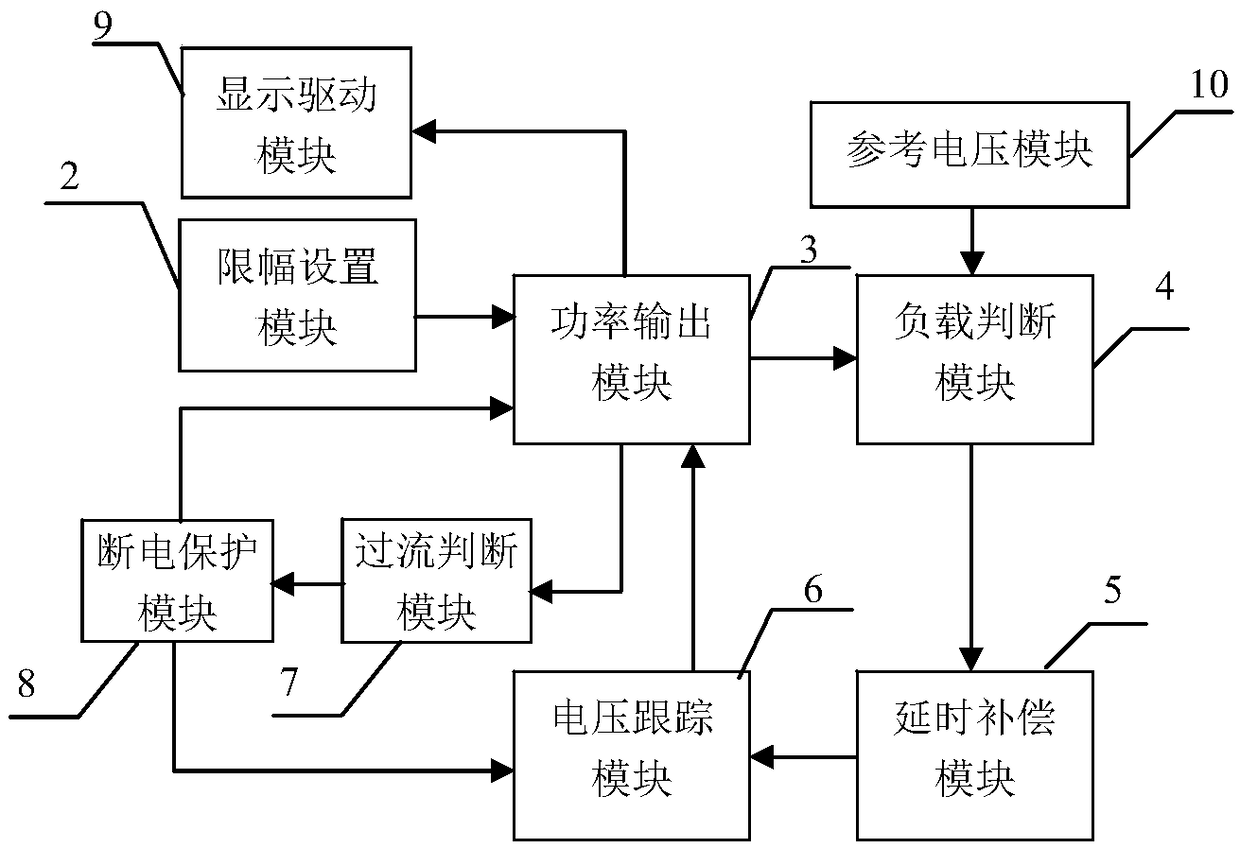
[0036] Embodiment 1 Overall structure of the present invention
[0037] Overall structure of the present invention is as figure 1 As shown, the structure includes front panel 1, limiter setting module 2, power output module 3, load judging module 4, delay compensation module 5, voltage tracking module 6, overcurrent judging module 7, power-off protection module 8, display driver Module 9, reference voltage module 10; limit setting module 2 is connected with power output module 3, power output module 3 is connected with display drive module 9, load judgment module 4, overcurrent judgment module 7 respectively, reference voltage module 10 is connected with load judgment module The modules 4 are connected, the load judgment module 4 is connected with the delay compensation module 5, the delay compensation module 5 is connected with the voltage tracking module 6, the voltage tracking module 6 is connected with the power output module 3, the overcurrent judgment module 7 is connect...
Embodiment 2
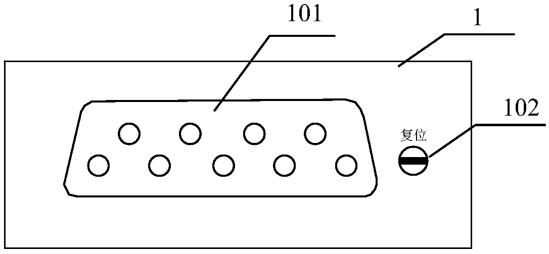
[0038] Embodiment 2 Front panel of the present invention
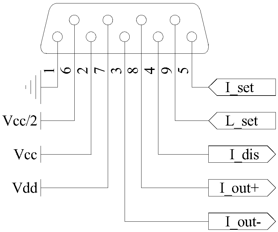
[0039] Front panel structure of the present invention such as figure 2 As shown, the structure of the front panel 1 includes: a 9-pin D-shaped interface 101 and a reset button 102; the pin connection relationship of the 9-pin D-shaped interface 101 is as follows image 3 As shown, pin 1 is grounded, pin 6 is connected to power supply Vcc / 2, pin 2 is connected to power supply Vcc, pin 7 is connected to power supply Vdd, pin 3 and pin 8 are respectively connected to port PWR-out3 and port PWR-out2 of power output module 3, Pin 4 is connected to the port DIS-out of the display driver module 9 , pin 9 and pin 5 are respectively connected to the port L_set and the port I_set of the limiter setting module 2 .
[0040] Among them, the 9-pin D-shaped interface 101 facilitates the integrated connection between the present invention and other equipment, and when connected with other equipment, the external equipment provides t...
Embodiment 3
[0041] Embodiment 3 Limit setting module of the present invention
[0042] Limiter setting module 2 of the present invention belongs to the prior art, and can be conventionally designed according to actual needs, and can also adopt the structure provided by this embodiment, such as Figure 4 As shown, one end of the resistor R39 is used as an input end of the limiter setting module 2, which is recorded as the port I_set, connected to pin 5 of the 9-pin D-shaped interface 101 on the front panel 1, and the other end of the resistor R39 is connected to the non-inverting input of the operational amplifier U10B terminal and the positive pole of diode D2, the negative pole of diode D2 is connected to the output terminal of operational amplifier U10A and one end of resistor R38, the other end of resistor R38 is connected to the inverting input terminal of operational amplifier U11A, the non-inverting input terminal of operational amplifier U10A is connected to one end of resistor R37 ...
PUM
 Abstract
Description
Claims
Application Information