A simulation method and system for complex boundary micro-flow

A simulation method and micro-flow technology, which are applied in the field of simulation methods and systems for micro-flow with complex boundaries, can solve the problems that micro-scale flow cannot be simulated, the gas velocity and temperature are different from the boundary, and the exchange of momentum and energy is incomplete. Achieve the effect of rigorous algorithm, small calculation amount, and small algorithm complexity

Inactive Publication Date: 2019-03-19
CHINA PETROLEUM & CHEM CORP +1
View PDF3 Cites 5 Cited by
  • Summary
  • Abstract
  • Description
  • Claims
  • Application Information

AI Technical Summary

Problems solved by technology

Although the probability of collision between methane gas molecules is still greater than the probability of collision with the solid surface, the momentum and energy exchange of the gas molecules after the collision at the solid surface is not complete at this time, resulting in the velocity and temperature of the gas on the solid surface and the boundary Different, resulting in speed slip and temperature jump
The Navier-Stokes equation can still describe the changes in the flow field and temperature field in this region, but it needs to use the boundary conditions of velocity slip and temperature jump for correction calculation
[0006] (3) Transition flow (Transition flow, 0.1
However, the above three types of models are only suitable for simple two-dimensional straight channels, and cannot achieve accurate simulation calculations for micro-scale flows in porous structures with complex boundaries (such as tight shale, tight sandstone, etc.)

Method used


Image

  • A simulation method and system for complex boundary micro-flow
  • A simulation method and system for complex boundary micro-flow
  • A simulation method and system for complex boundary micro-flow

Examples


Embodiment 1

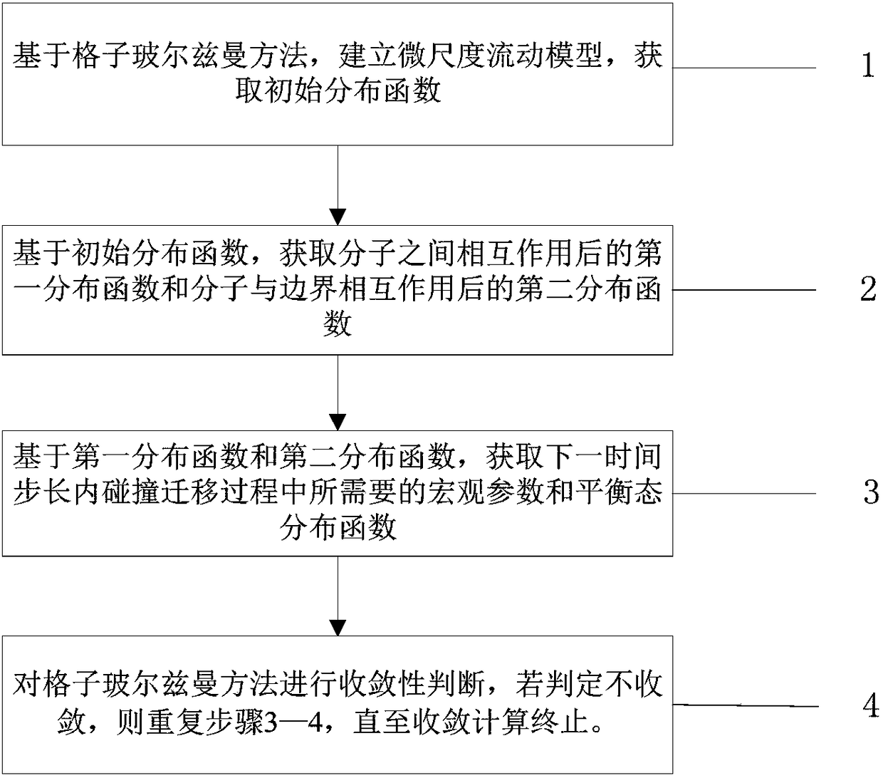
[0042] In this embodiment, the method for simulating complex boundary microflow according to the present invention may include: 1) establishing a microscale flow model based on the lattice Boltzmann method, and obtaining an initial distribution function; 2) obtaining molecules based on the initial distribution function The first distribution function after the interaction between the molecules and the second distribution function after the interaction between the molecules and the boundary; 3) Based on the first distribution function and the second distribution function, obtain the required collision migration process in the next time step. Macro parameters and equilibrium state distribution function; 4) Convergence judgment of the lattice Boltzmann method, if it is judged not to converge, repeat steps 3-4 until the convergence calculation is terminated.

[0043] This embodiment uses the lattice Boltzmann method to establish a micro-scale flow model, and realizes the simulation...

application example 1

[0074] To facilitate understanding of the solutions and effects of the embodiments of the present invention, a specific application example is given below. It will be understood by those skilled in the art that this example is provided only to facilitate understanding of the invention and that any specific details thereof are not intended to limit the invention in any way.

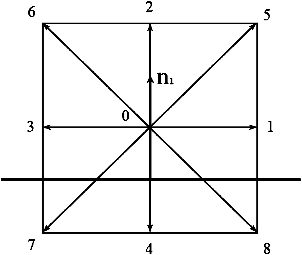
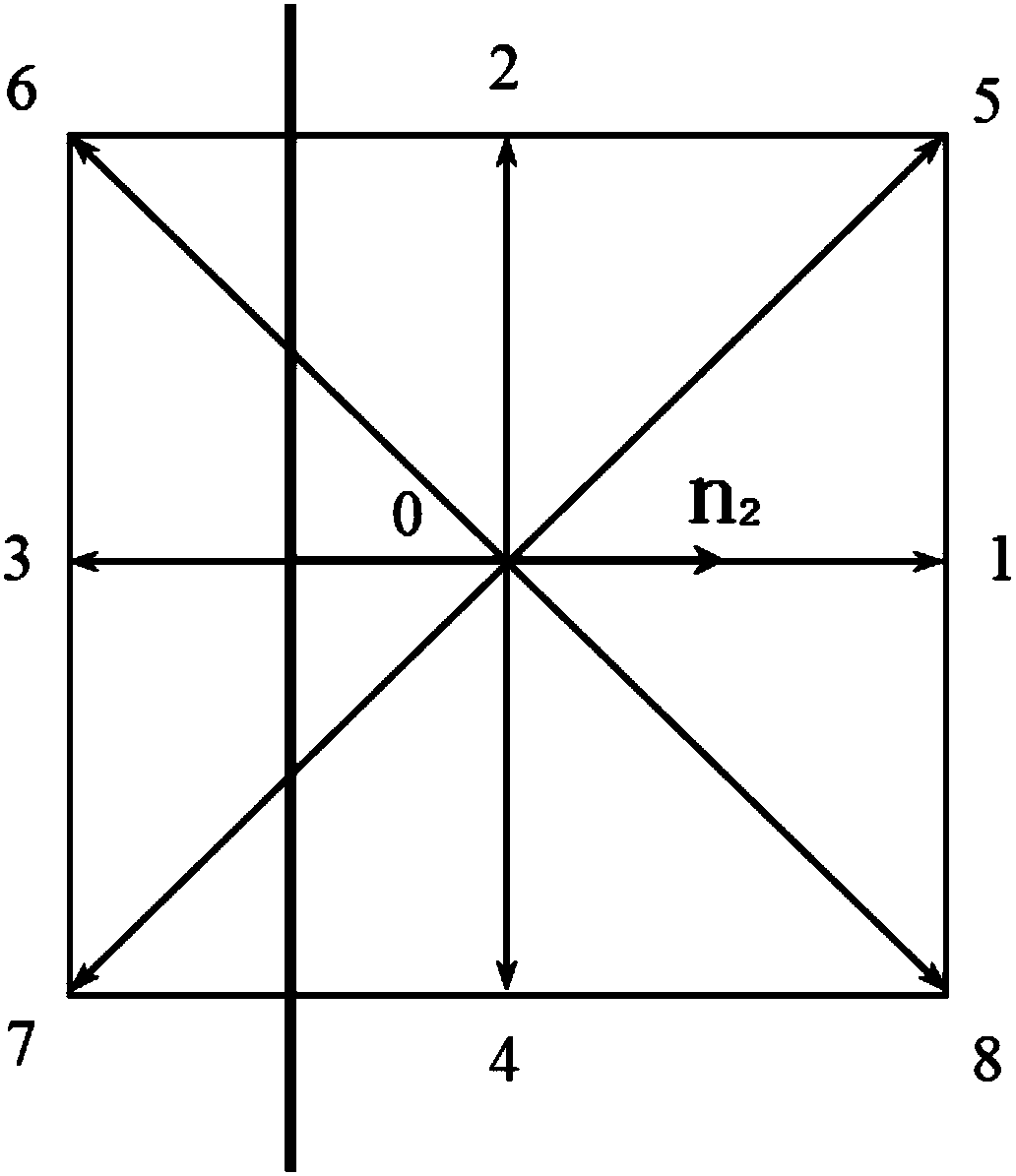
[0075] figure 2 A schematic diagram showing the first boundary case of micro-scale flow in two-dimensional space according to an embodiment of the present invention, image 3 A schematic diagram showing the second boundary case of micro-scale flow in two-dimensional space according to an embodiment of the present invention, Figure 4 A schematic diagram showing the third boundary case of two-dimensional space micro-scale flow according to an embodiment of the present invention, Figure 5 A schematic diagram showing the fourth boundary case of micro-scale flow in two-dimensional space according to an emb...

application example 2

[0096] Image 6 A schematic diagram of a three-dimensional space micro-scale flow boundary processing format according to an embodiment of the present invention is shown.

[0097] First, based on the lattice Boltzmann method, a micro-scale flow model is established, and the whole field is initialized according to the given initial macro parameters and boundary conditions to obtain the initial distribution function represented by formula (1). Second, based on the initial distribution function, Obtain the first distribution function after the interaction between molecules and the second distribution function after the interaction between the molecules and the boundary. The first distribution function can be calculated by formula (2) and formula (3), and the second distribution function is obtained by For the acquisition of the boundary processing method, the specific process of acquiring the second distribution function by using the method proposed by the present invention will ...


PUM


Abstract

The invention discloses a simulation method and a system for complex boundary micro-flow, comprising the following steps: 1) based on a lattice Boltzmann method, establishing a micro-scale flow modeland obtaining an initial distribution function; 2) obtaining a first distribution function after that interaction between the molecule and a second distribution function after the interaction betweenthe molecules and the boundary based on the initial distribution function; 3) obtaining the macroscopic parameters and the equilibrium distribution function require in the next time step internal collision migration process based on the first distribution function and the second distribution function; 4) determining the convergence of the lattice Boltzmann method, and if it is determined that theconvergence of the lattice Boltzmann method is not carried out, the steps 3-4 are repeated until the convergence calculation is terminated. Compared with the existing LBM model for calculating micro-scale flow, the present invention can process cases with complex structure boundary conditions while satisfying physical reality and accuracy, and the model is more concise and has smaller algorithm complexity and calculation amount.

Description

technical field [0001] The invention belongs to the field of tight gas and shale gas development, and more particularly relates to a simulation method and system for complex boundary micro-flow. Background technique [0002] Compared with conventional oil and gas reservoirs, shale reservoirs have extremely low matrix permeability, and shale gas reservoirs have different gas characteristics, physical properties and mechanical properties. The multi-scale migration mechanisms of shale gas mainly include: molecular-scale Knudsen diffusion inside and on the surface of kerogen, rarefied gas flow in shale micro- and nano-scale pores, and conventional viscous flow in macro-scale large fractures. Then, a deep understanding of the multi-scale migration mechanism in the process of shale gas exploitation is of great significance for the effective exploitation of shale gas and the establishment of an efficient "well factory" development model. [0003] Nano-scale pores are the main stor...

Claims


Application Information

Patent Timeline
Patent Type & Authority Applications(China)
IPC IPC(8): G06F17/50
CPCG06F30/20
Inventor 高诚龙秋莲孙川翔
Owner CHINA PETROLEUM & CHEM CORP
Why Eureka
Try Eureka