Electric automobile double-motor driving system and control method thereof
A dual-motor drive, electric vehicle technology, applied in electric vehicles, control drives, control devices, etc., can solve problems such as low motor power consumption efficiency
- Summary
- Abstract
- Description
- Claims
- Application Information
AI Technical Summary
Problems solved by technology
Method used
Image
Examples
Embodiment 1
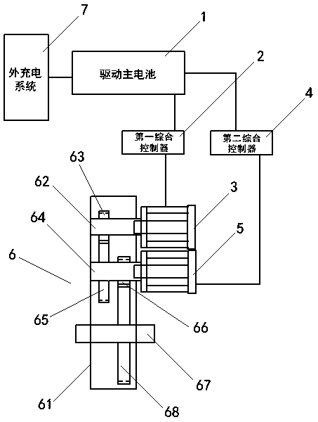
[0049] see figure 1 As shown, a dual-motor drive system for an electric vehicle includes a drive main battery 1 , a first integrated controller 2 , a first drive motor 3 , a second integrated controller 4 , a second drive motor 5 and a double-input gearbox 6 .
[0050] The double-input reduction box 6 consists of a casing 61, a first input shaft 62, a first driving gear 63, a second input shaft 64, a second driving gear 65, a first driven gear 66, an output shaft 67 and a second driven gear. Moving gear 68 forms.
[0051] The first input shaft 62 , the second input shaft 64 and the output shaft 67 are arranged in parallel in order from top to bottom in the box body 61 , and the first driving gear 63 is sheathed on the first drive gear 63 . On an input shaft 62, the second driving gear 65 and the first driven gear 66 are sleeved on the second input shaft 64, and the second driven gear 68 is sleeved on the output shaft 67 , and the first driving gear 63 meshes with the first d...
Embodiment 2
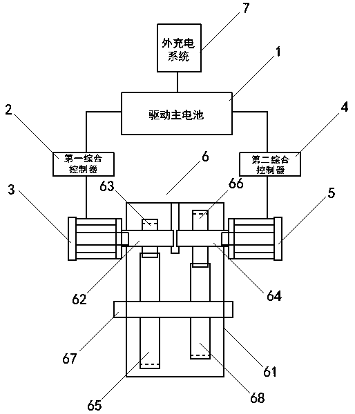
[0059] see figure 2 As shown, a dual-motor drive system for an electric vehicle includes a drive main battery 1 , a first integrated controller 2 , a first drive motor 3 , a second integrated controller 4 , a second drive motor 5 and a double-input gearbox 6 .
[0060] The double-input reduction box 6 consists of a casing 61, a first input shaft 62, a first driving gear 63, a second input shaft 64, a second driving gear 65, a first driven gear 66, an output shaft 67 and a second driven gear. Moving gear 68 forms.
[0061] The first input shaft 62 , the second input shaft 64 and the output shaft 67 are horizontally arranged in the box body 61 , and the first input shaft 62 and the second input shaft 64 are respectively located at the The left and right ends above the output shaft 67, the first driving gear 63 is sleeved on the first input shaft 62, the second driving gear 65 is sleeved on the second input shaft 64, the The first driven gear 66 and the second driven gear 68 a...
Embodiment 3
[0065]In Embodiment 1, the speed ratio of the first driving gear 63 to the first driven gear 66 is 2.2, and the speed ratio of the second driving gear 65 to the second driven gear 68 is 5.8 is a preferred embodiment, the reduction ratio of the low gear is calculated as 2.2*5.8=12.76, the reduction ratio of the high gear is 5.8, and the empty vehicle is calculated as 600 kg, then the first drive motor 3 responsible for the low gear is estimated to support a maximum speed of 25 ~30 kilometers, the speed that the second drive motor 5 that is responsible for the high speed gear can support is 30~70 kilometers per hour.
[0066] It should be noted that due to the large speed difference between the two motors, the selection of bearings in actual use needs to take into account the carrying capacity of the no-load speed. For example, the rated speed of the motor is 3000. When the vehicle is running at high speed, the idling speed of the first driving motor is likely to reach more than...
PUM
 Abstract
Description
Claims
Application Information
 - R&D
- Intellectual Property
- Life Sciences
- Materials
- Tech Scout
- Unparalleled Data Quality
- Higher Quality Content
- 60% Fewer Hallucinations
Browse by: Latest US Patents, China's latest patents, Technical Efficacy Thesaurus, Application Domain, Technology Topic, Popular Technical Reports.
© 2025 PatSnap. All rights reserved.Legal|Privacy policy|Modern Slavery Act Transparency Statement|Sitemap|About US| Contact US: help@patsnap.com


