
Wind power piezoelectric electric generator

A generator and piezoelectric technology, applied in the direction of wind power generators, wind power generation, wind power storage, etc., can solve the problems of narrow effective working range, non-utilization of miniaturization, large starting torque, etc., to improve energy collection efficiency, The effect of widening the working range of wind speed and reducing the starting wind speed

Pending Publication Date: 2019-03-22
SUZHOU VOCATIONAL UNIV
View PDF6 Cites 5 Cited by
  • Summary
  • Abstract
  • Description
  • Claims
  • Application Information

AI Technical Summary

Problems solved by technology

[0003] Most of the currently developed wind turbines are driven by windmills, and the piezoelectric vibrator is excited to generate electricity through indirect excitation components (picks, protruding teeth or steel balls, magnets); however, since there are many intermediate components involved, Not only is there serious friction loss, but it also produces noise and requires a large starting torque; especially when the size of the generator is smaller, the processing and assembly of the components are more complicated, the proportion of friction loss is greater, and the wear of accessories is also greater. serious
When magnets are used to form non-contact excitation, although the power generation efficiency and adaptability are improved to a certain extent, and the starting torque is reduced, friction loss and hidden troubles between rotating parts cannot be avoided, and the power generation device cannot be effectively reduced. In addition, this type of wind-induced piezoelectric generator has only one optimal excitation frequency matching the natural frequency, and the effective working range is narrow; therefore, this type of wind-induced piezoelectric generator has a complex structure, large starting torque, and low wind energy utilization , short life, narrow bandwidth, and does not take advantage of miniaturization

Method used


Image

  • Wind power piezoelectric electric generator
  • Wind power piezoelectric electric generator
  • Wind power piezoelectric electric generator

Examples


Embodiment 1

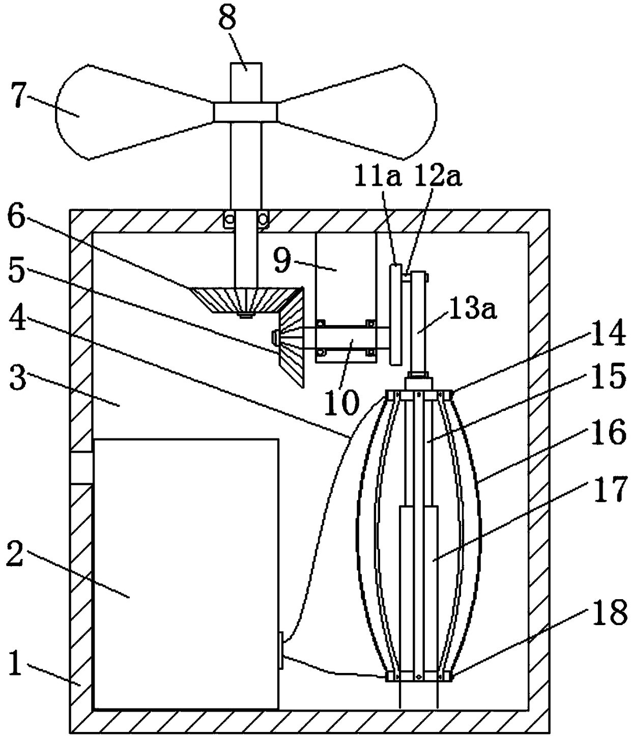
[0019] attached figure 1 The wind-driven piezoelectric generator according to the present invention includes a housing 1, a sealed space 3 located in the housing 1, a drive shaft 8 vertically arranged on the upper end of the housing 1 and extending into the sealed space 3 at the lower end, and arranged in the The blade 7 at the upper end of the driving shaft 8, the driving bevel gear 6 arranged at the lower end of the driving shaft 8, the driven shaft 10 fixed horizontally in the sealed space 3 and fixed by the bracket 9, the driven shaft 10 arranged at one end of the driven shaft 10 and connected with the driving bevel gear 6 meshed driven bevel gear 5, fixed rod 17 vertically fixed at the bottom of the sealed space 3, movable rod 15 sleeved on the fixed rod 17 and can slide up and down along the fixed rod 17, set at the other end of the driven shaft 10 The reciprocating mechanism for driving the movable rod 15 to move up and down, the upper support ring 14 arranged on the up...

Embodiment 2

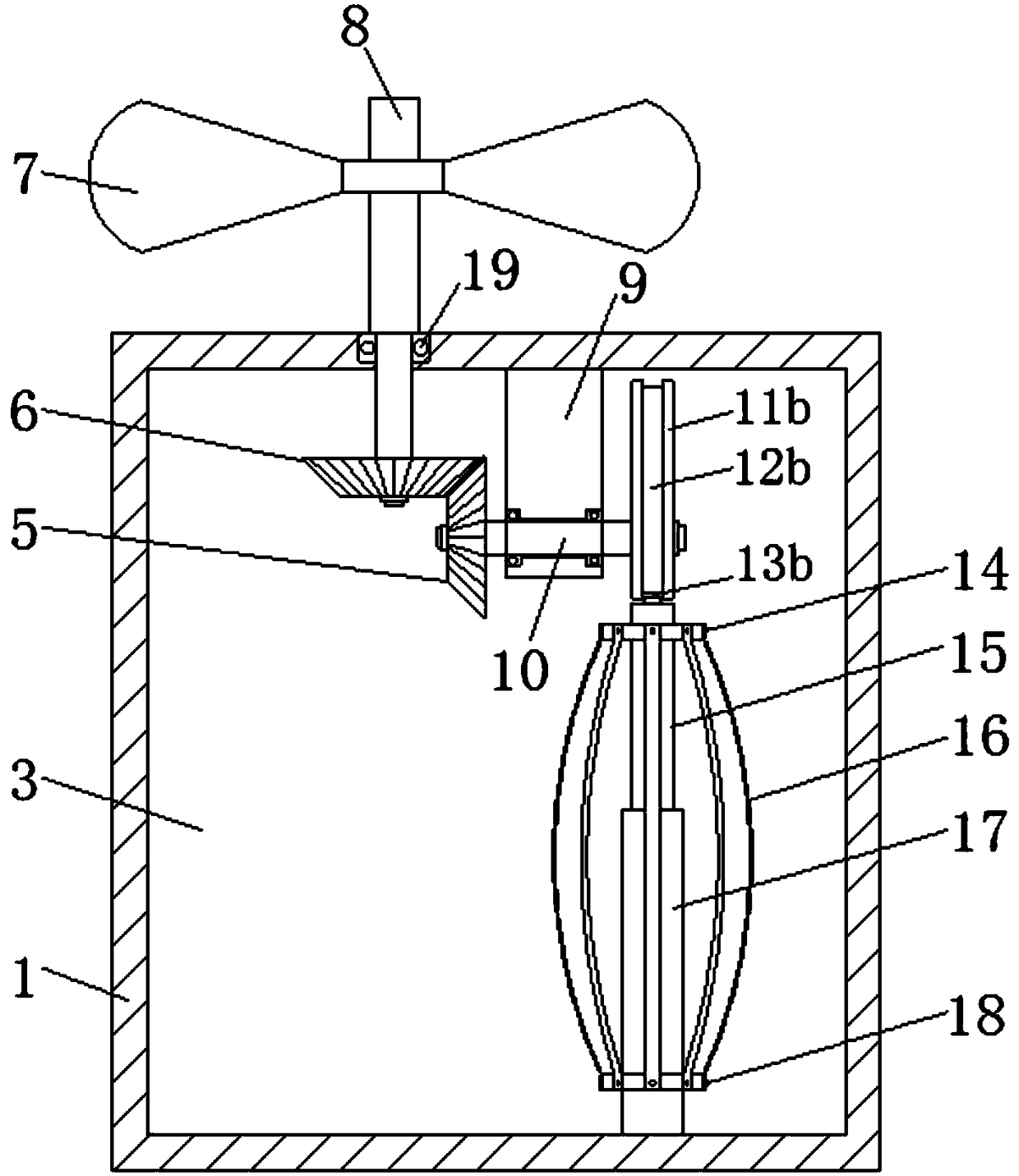
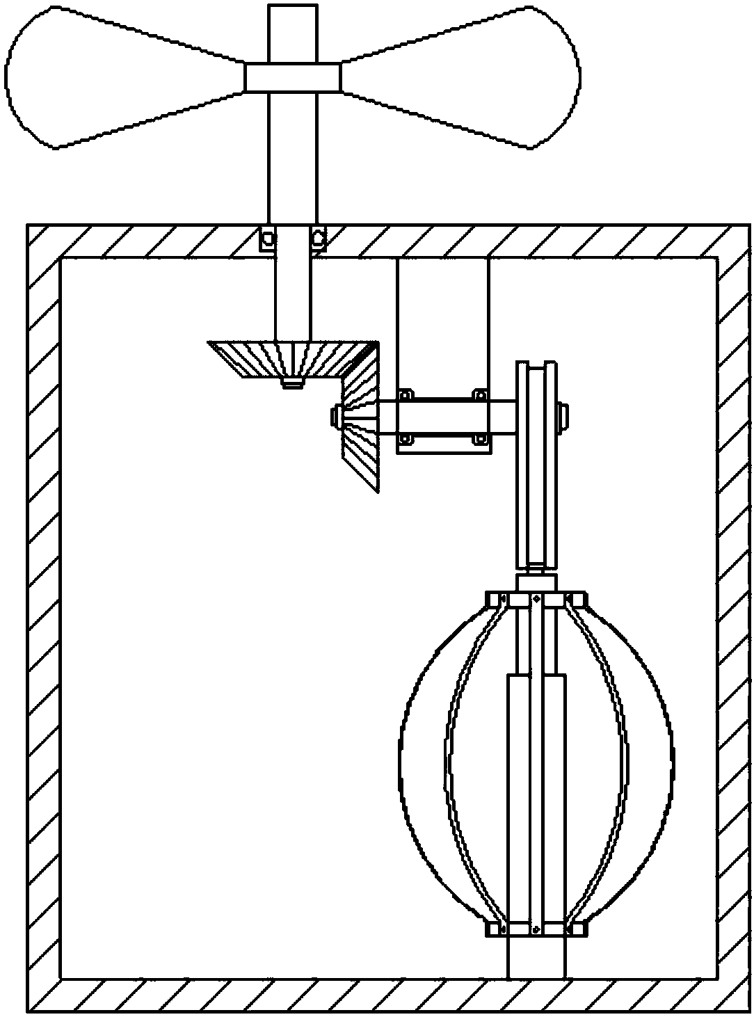
[0022] attached Figure 2-4 The wind-driven piezoelectric generator according to the present invention includes a housing 1, a sealed space 3 located in the housing 1, a driving shaft 8 vertically arranged on the upper end of the housing 1 and extending into the sealed space 3 at the lower end, and arranged in the The blade 7 at the upper end of the driving shaft 8, the driving bevel gear 6 arranged at the lower end of the driving shaft 8, the driven shaft 10 fixed horizontally in the sealed space 3 and fixed by the bracket 9, the driven shaft 10 arranged at one end of the driven shaft 10 and connected with the driving bevel gear 6 meshed driven bevel gear 5, fixed rod 17 vertically fixed at the bottom of the sealed space 3, movable rod 15 sleeved on the fixed rod 17 and can slide up and down along the fixed rod 17, set at the other end of the driven shaft 10 The reciprocating mechanism for driving the movable rod 15 to move up and down, the upper support ring 14 arranged on t...


PUM


Abstract

The invention relates to a wind power piezoelectric electric generator. The wind power piezoelectric electric generator comprises a shell, a sealed space located in the shell, a driving shaft which isvertically arranged at the upper end of the shell and extends into the sealed space, blades arranged on the driving shaft, a driven shaft which is horizontally arranged in the sealed space and fixedthrough a bracket, a driving bevel gear and a driven bevel gear which connect the driving shaft with the driven shaft, fixed rods which are vertically fixed to the bottom of the sealed space, moving rods which are arranged on the fixed rods in a sleeving mode, a reciprocating mechanism arranged on the driven shaft for driving the moving rods to move vertically, an upper supporting ring arranged atthe upper ends of the moving rods, a lower supporting ring arranged at the lower ends of the fixed rods and a plurality of piezoelectric patches with two ends arranged on the upper supporting ring and the lower supporting ring correspondingly. According to the wind power piezoelectric electric generator, under the action of wind power, the blades can drive the reciprocating mechanism to drive themoving rods to move vertically, the piezoelectric patches are subjected to deformation, electric energy is excited, and the wind power piezoelectric electric generator has the advantages that the structure is simple, the size is small, the manufacturing is easy, the starting torque is low, the service life is long, and miniaturization is convenient.

Description

technical field [0001] The invention relates to the field of new energy, in particular to a wind-driven piezoelectric generator. Background technique [0002] There are a variety of green energy in nature, among which wind energy has attracted much attention due to its abundant reserves, cleanness, safety and wide distribution; the forms of wind energy conversion mainly include electromagnetic, electrostatic and piezoelectric, among which piezoelectric is simple in structure , small size, no pollution, high energy density, easy to manufacture, low cost, easy to achieve integration and miniaturization, and can meet the needs of micro devices. [0003] Most of the currently developed wind turbines are driven by windmills, and the piezoelectric vibrator is excited to generate electricity through indirect excitation components (picks, protruding teeth or steel balls, magnets); however, since there are many intermediate components involved, Not only is there serious friction los...

Claims


Application Information

Patent Timeline
IPC IPC(8): F03D9/11F03D15/00H02N2/18
CPCH02N2/185F03D9/11F03D15/00Y02E10/72Y02P70/50Y02E70/30
Inventor 孙春华尚广庆汪红兵
Owner SUZHOU VOCATIONAL UNIV
Learn More