
Wind-light-fuel-storage integrated power generation device and method

A power generation device, photovoltaic power generation technology, applied in photovoltaic power generation, photovoltaic power station, photovoltaic module and other directions, can solve the problems of unstable power supply of fuel generators, lack of integrated installation structure, complicated installation and debugging, etc., to achieve superior energy management, Eliminate the installation and commissioning process, and the effect of stable and reliable energy supply

Inactive Publication Date: 2019-03-22
48TH RES INST OF CHINA ELECTRONICS TECH GROUP CORP
View PDF3 Cites 0 Cited by
  • Summary
  • Abstract
  • Description
  • Claims
  • Application Information

AI Technical Summary

Problems solved by technology

[0002] In areas without electricity or unstable power grids, power supply is usually powered by fuel generators, which are unstable, polluting, expensive, and require frequent refueling
At present, some solutions use solar energy, wind energy, etc. for power generation, and use batteries for energy storage, or use mains power as backup energy, but they do not have an integrated installation structure when in use, occupy a large area and are cumbersome to install and debug; When the resources are insufficient, the mains power must be used as a backup power supply, which is not suitable for use in places without mains power

Method used


Image

  • Wind-light-fuel-storage integrated power generation device and method
  • Wind-light-fuel-storage integrated power generation device and method
  • Wind-light-fuel-storage integrated power generation device and method

Examples


Embodiment Construction

[0027] The present invention will be further described below in conjunction with the drawings and specific embodiments of the specification.

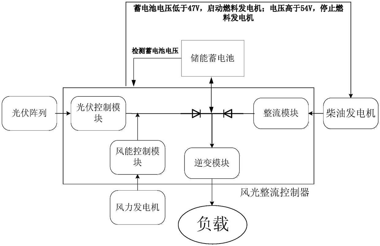
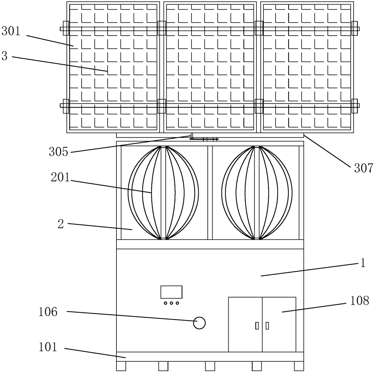
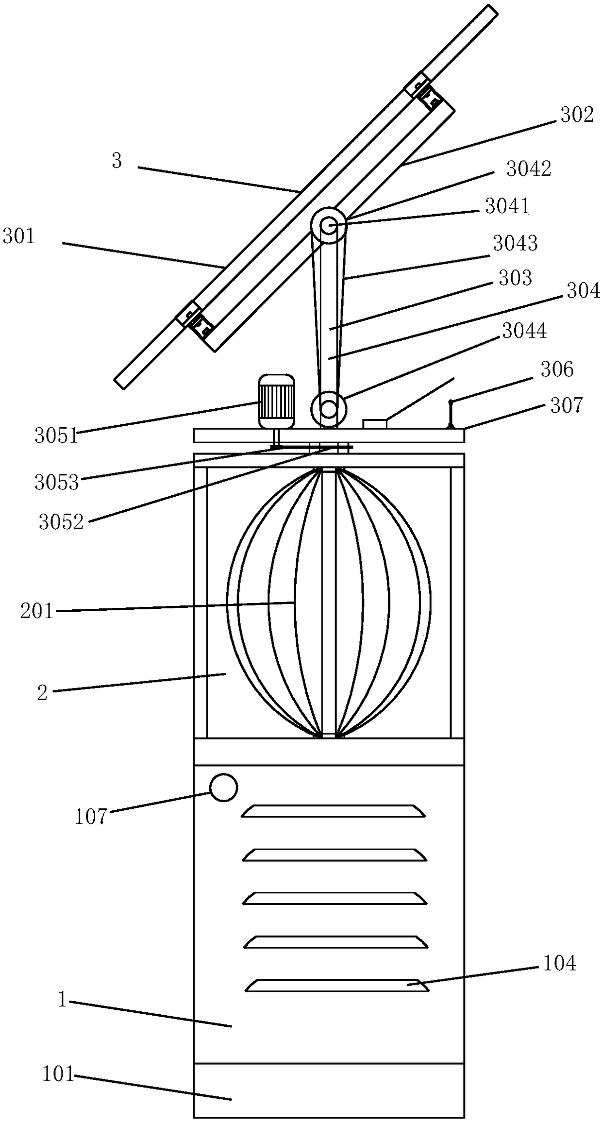
[0028] Such as Figure 1 to Figure 4 As shown, the wind-solar-fired-storage integrated power generation device of this embodiment includes a bottom cabin 1, a middle cavity 2 and a photovoltaic power generation unit 3. The bottom cabin 1 is equipped with a fuel generator 102 and an energy storage unit 113 (such as a battery ); The middle cavity 2 is installed above the bottom cabin 1, a wind generator 201 is installed in the middle cavity 2; the photovoltaic power generation unit 3 is located above the middle cavity 2, and the photovoltaic power generation unit 3 includes a base 307 and a photovoltaic module 301 The inclination angle adjustment mechanism 304 is installed between the photovoltaic module 301 and the base 307 to adjust the inclination angle of the photovoltaic module 301; an azimuth adjustment mechanism 305 is provided betwee...


PUM


Abstract

The invention discloses a wind-light-fuel-storage integrated power generation device, comprising a bottom cabin body, a middle-layer cavity body and a photovoltaic power generation unit, wherein a fuel generator and an energy storage unit are arranged in the bottom cabin body; the middle-layer cavity is arranged above the bottom cabin body and is provided with a wind turbine inside; the photovoltaic power generation unit is installed above the middle-layer cavity body and comprises a base and a photovoltaic component, and an inclination angle adjusting mechanism is installed between the photovoltaic component and the base; and an azimuth angle adjusting mechanism is arranged between the base and the middle-layer cavity body. The invention also discloses a power generation method. When solar energy or wind energy is sufficient, electricity is generated for use by a load, and excess electric energy is stored in the energy storage unit. When both solar energy and wind energy are insufficient, the electric energy in the energy storage unit is utilized to combine with solar energy and wind energy to supply power to the load. When the electric energy in the energy storage unit is exhausted, the fuel generator supplies power to the load. When the storage unit is full, the fuel generator stops generating electricity. The device and the method of the invention have the advantages of simple structure, reasonable layout and the like.

Description

Technical field [0001] The present invention mainly relates to the technical field of power supply, in particular to a wind-solar, fuel-storage integrated power generation device and method. Background technique [0002] In areas where there is no electricity or the grid is unstable, the power supply is usually powered by fuel generators, which are unstable, pollute, costly and require frequent refueling. At present, some of the solutions use solar energy, wind energy, etc. for power generation, and use batteries for energy storage, or use city electricity as backup energy, but they do not have an integrated installation structure when used, occupy a large area and cumbersome installation and debugging; When resources are insufficient, the utility power is required as a backup power source, which is not suitable for use in places without utility power. Summary of the invention [0003] The technical problem to be solved by the present invention is: in view of the technical proble...

Claims


Application Information

Patent Timeline
Patent Type & Authority Applications(China)
IPC IPC(8): H02S10/12H02S20/30
CPCH02S10/12H02S20/30Y02E10/50
Inventor 郭进陆运章胡晓宇周洪彪蒋超马一山张佳亮黄齐鸣周蒙
Owner 48TH RES INST OF CHINA ELECTRONICS TECH GROUP CORP
Learn More