Laser die cutting machine
A laser die-cutting and die-cutting machine technology, applied in laser welding equipment, welding equipment, metal processing, etc., can solve the problems of low efficiency, low precision, and limited length of processed materials in the die-cutting process, and achieve high automation, Improve die-cutting precision and achieve effective control
- Summary
- Abstract
- Description
- Claims
- Application Information
AI Technical Summary
Problems solved by technology
Method used
Image
Examples
Embodiment 1
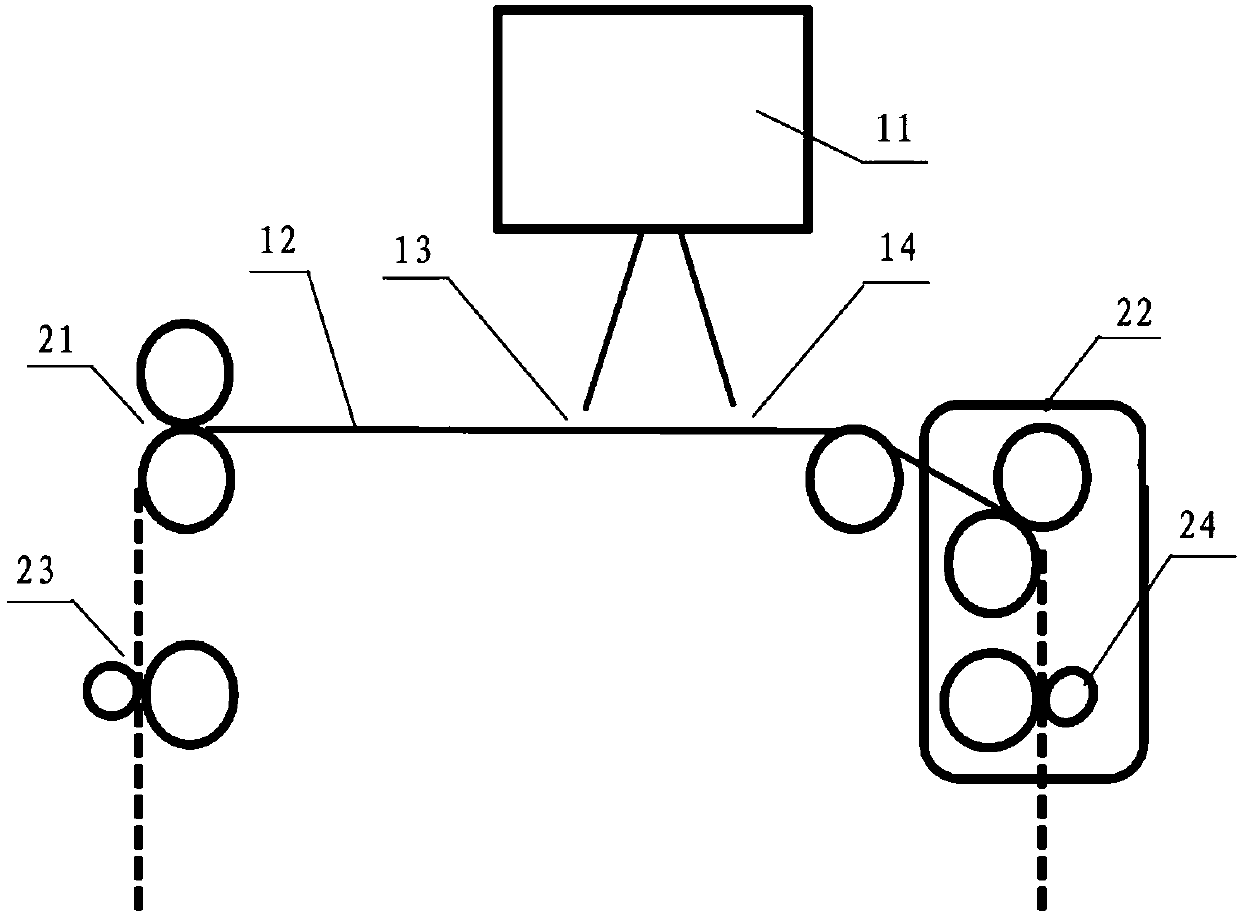
[0037] as attached figure 1 As shown, it is a structural schematic diagram of a laser die-cutting machine in this embodiment. The laser die-cutting machine in this embodiment includes a laser 11, a servo motor, and a reciprocating feeding system. The reciprocating feeding system includes a traction device and a driven device. The servo motor controls the operation of the reciprocating feeding system. In this embodiment, the traction device is a traction roller 22, the driven device is a driven roller 21, the traction roller 22 is close to the side of the discharge port 14, and the driven roller 21 is close to the side of the feed port 13; the traction roller 22 cooperates with the driven roller 21 to make the material 12 move back and forth: to make the material 12 move longitudinally to the first direction or to the second direction; The direction of the material outlet 14 moves; when the driven roller 21 receives the material and the traction roller 22 discharges the materi...
Embodiment 2
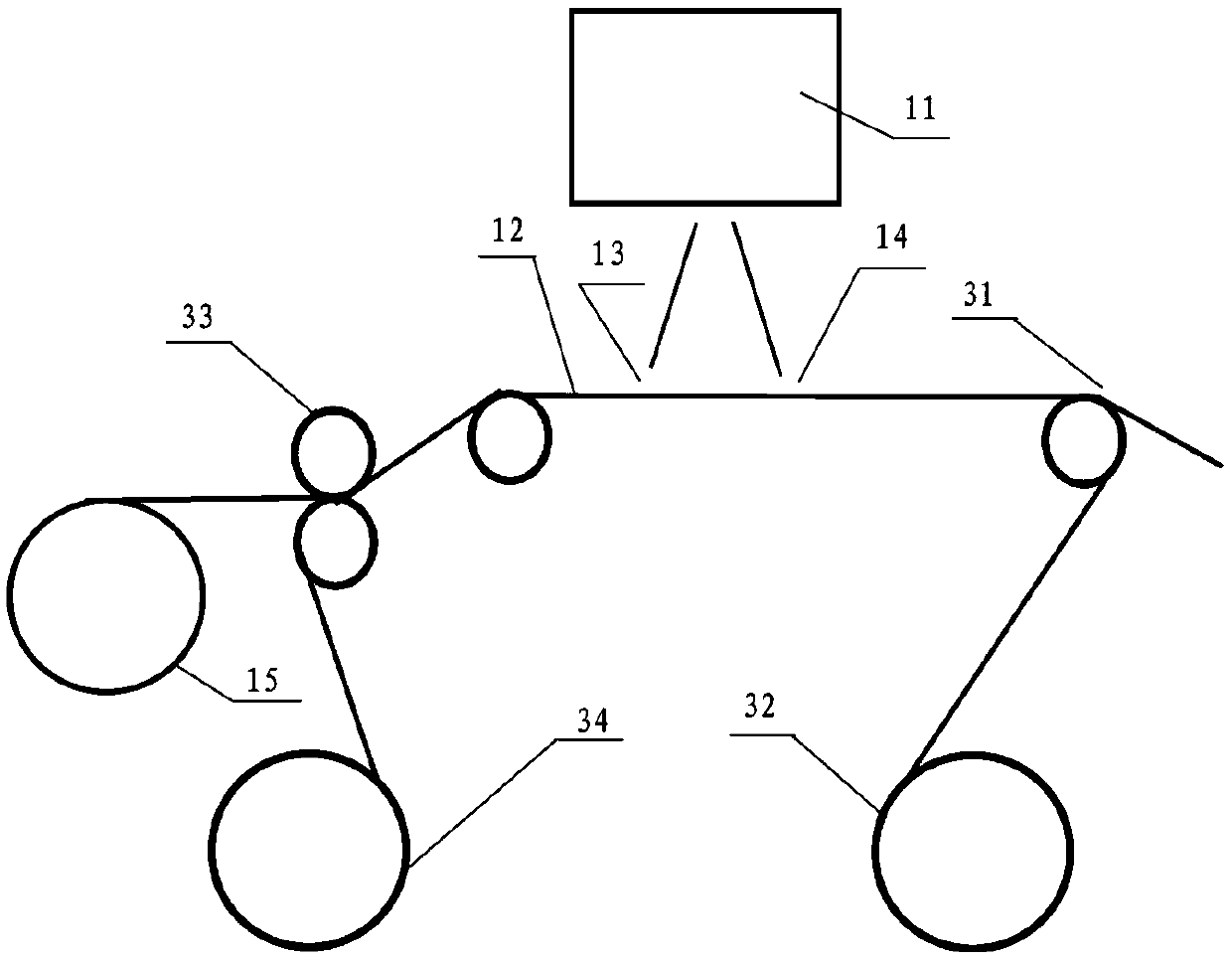
[0044] as attached figure 2 Shown is a schematic structural view of a laser die-cutting machine provided in this embodiment. It can be seen from the figure that the laser die-cutting machine provided in this embodiment includes a main discharge shaft 15 and a lower compound removal system. The main discharge shaft 15 is close to the feed port 13 . Described lower compound throwing off system comprises compounding device and throwing off device; Said compounding device is positioned between main discharging shaft 15 and feed port 13 in the present embodiment, and described compounding device comprises compounding roller 33 and composite material discharging Axis 34; the peeling device is close to the discharge port 14 of the laser die-cutting machine, and the peeling device is located below the material after die-cutting by the laser 11. The peeling device in this embodiment includes a first peeling separation Roller 31 and first take-up shaft 32 .
[0045] Among them, the c...
Embodiment 3
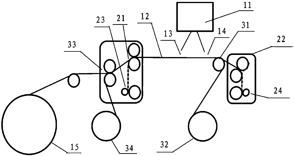
[0049] as attached image 3 As shown, it is a schematic structural diagram of a laser die-cutting machine provided in this embodiment. The laser die-cutting machine provided in this embodiment includes the reciprocating feeding system of Embodiment 1 and the lower compound peeling system of Embodiment 2. The reciprocating feeding system and the composite peeling off system will not be repeated here. Obviously, the laser die-cutting machine provided in this embodiment has the functions of the laser die-cutting machine provided in Embodiment 1 and Embodiment 2. Here, only the difference Brief description here.
[0050] as attached image 3 As shown, the composite roll 33 and the composite material discharge shaft 34 are located between the main discharge shaft 5 and the composite device is located between the main discharge shaft 15 and the driven roller 21, and the driven roller 21 is close to the feed port 13; the first The separation roller 31 and the first winding shaft 32...
PUM
 Abstract
Description
Claims
Application Information
 - R&D
- Intellectual Property
- Life Sciences
- Materials
- Tech Scout
- Unparalleled Data Quality
- Higher Quality Content
- 60% Fewer Hallucinations
Browse by: Latest US Patents, China's latest patents, Technical Efficacy Thesaurus, Application Domain, Technology Topic, Popular Technical Reports.
© 2025 PatSnap. All rights reserved.Legal|Privacy policy|Modern Slavery Act Transparency Statement|Sitemap|About US| Contact US: help@patsnap.com


