Tire mold laser cleaning light path

A tire mold and laser cleaning technology, applied in the field of laser cleaning, can solve the problems of safety and environmental protection, long cleaning time, easy damage to mold precision, etc., to improve efficiency, avoid mold damage, and save standby time.

Active Publication Date: 2019-03-26
SHENYANG POLYTECHNIC UNIV
View PDF4 Cites 5 Cited by
  • Summary
  • Abstract
  • Description
  • Claims
  • Application Information

AI Technical Summary

Problems solved by technology

Traditional cleaning methods include sand blasting, ultrasonic or carbon dioxide cleaning, etc., but these methods usually have to cool the high-heat mold for several hours before moving it to the cleaning equipment for cleaning, which takes a long time to clean and easily damages the precision of the mold , chemical solvents and noise will also cause safety and environmental issues

Method used


Image

  • Tire mold laser cleaning light path
  • Tire mold laser cleaning light path
  • Tire mold laser cleaning light path

Examples


Embodiment Construction

[0016] Attached below Figure 1-2 And embodiment further illustrate the present invention.

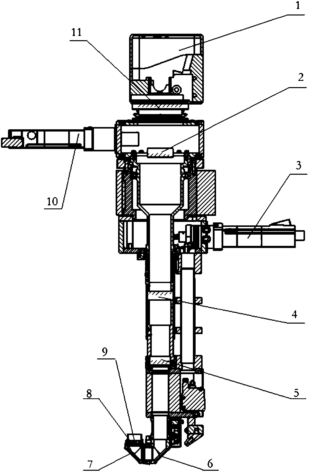
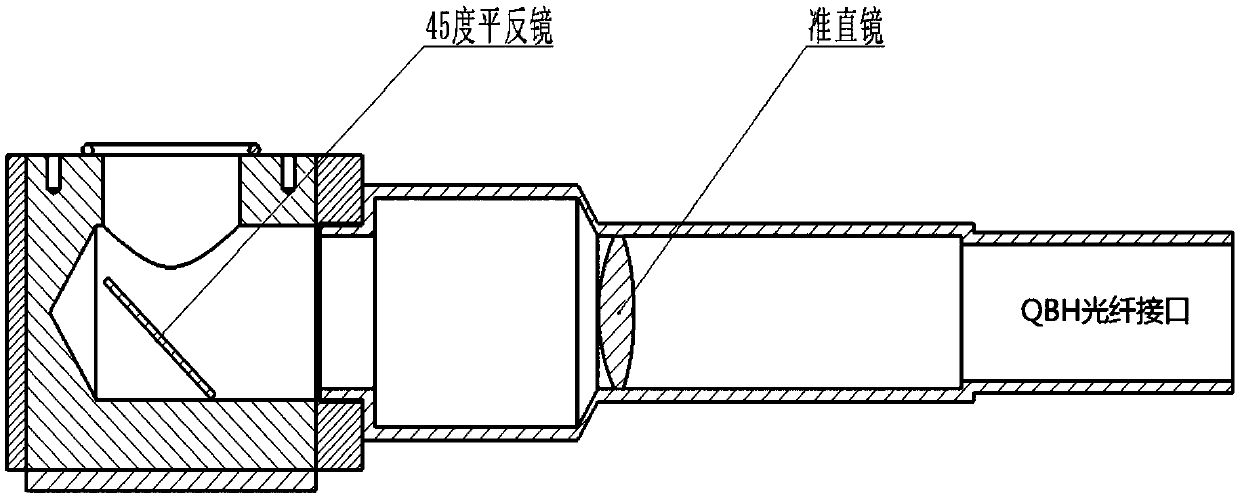
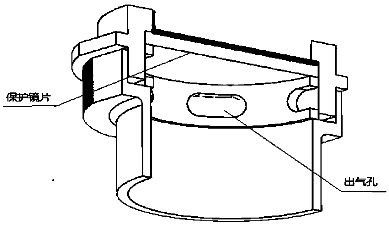
[0017] A tire mold laser cleaning optical path, the laser beam is transmitted through the optical fiber through the connection of the QBH interface, and the beam enters the optical path; the optical path includes a scanning vibrating mirror 1, a first plano-convex lens 2, a motor 3, a second plano-convex lens 4, and a double-convex lens 5, The first 45-degree flat mirror 6, the second 45-degree flat mirror 7, the protective lens 8, the gas protection device 9, the motor 10, the vibrating mirror window mirror 11; the beam enters the scanning vibrating mirror 1, and then the beam passes through the vibrating mirror window mirror 11. Transmission to the first plano-convex lens 2, with the convex surface facing upwards, converging the light beam to the focal point, then continuing to transmit and diverge, and passing it to the second plano-convex lens 4, with the convex surface facing down...


PUM


Abstract

The invention provides a tire mold laser cleaning light path. The tire mold laser cleaning light path comprises a scanning galvanometer, a plano-convex lens I, a motor, a plano-convex lens II, a biconvex lens, a first 45-degree plane mirror, a second 45-degree plane mirror, a protective lens, a gas protection device, a motor and a galvanometer window mirror. A light beam goes into the scanning galvanometer, then passes through the galvanometer window mirror and is transmitted to the first plano-convex lens. The convex surface faces upwards to gather the light beam to the focal point, and thenthe light beam is continuously transmitted and diffused to the second plano-convex lens. The convex surface faces downwards to turn the light beam into parallel light again. Different sizes of light spots, adjustable focal lengths and gas shield are provided and output from the interior of the light path and the length of the light path is extended to adapt to laser cleaning of different sizes oftire molds. The tire mold laser cleaning light path can realize different scanning tracks and focal lengths and can conduct full-automatic cleaning on the tire molds to achieve automation and improvethe efficiency.

Description

technical field [0001] The invention belongs to the technical field of laser cleaning, in particular to a tire mold laser cleaning optical path. Background technique [0002] Cleaning of tire molds: Tire manufacturers all over the world manufacture hundreds of millions of tires every year. Cleaning of tire molds must be fast and reliable during the production process to save downtime. Traditional cleaning methods include sand blasting, ultrasonic or carbon dioxide cleaning, etc., but these methods usually have to cool the high-heat mold for several hours before moving it to the cleaning equipment for cleaning, which takes a long time to clean and easily damages the precision of the mold , chemical solvents and noise will also produce safety and environmental issues. Using the laser cleaning method, because the laser can be transmitted by optical fiber, it is very flexible in use; because the laser cleaning method can be connected by optical fiber to guide the light to the d...

Claims


Application Information

Patent Timeline
Patent Type & Authority Applications(China)
IPC IPC(8): B29C33/72B08B7/00
CPCB08B7/0042B29C33/72Y02W30/62
Inventor 刘伟军王静高巍刘晓轩
Owner SHENYANG POLYTECHNIC UNIV
Why Eureka
Try Eureka