Cathode roller machine

A cathode roller and roller shaft technology, applied in the direction of electrodes, electrolytic coatings, phosphating, etc., can solve problems such as insufficient conductive capacity, impact on bearing life, poor conduction performance, etc., to reduce heat generation, meet continuous production, and improve stability sexual effect

Pending Publication Date: 2019-03-26
河南恒星钢缆股份有限公司
View PDF0 Cites 2 Cited by
  • Summary
  • Abstract
  • Description
  • Claims
  • Application Information

AI Technical Summary

Problems solved by technology

[0003] In the process of phosphating steel wire, it is necessary to use the steel wire as the negative electrode and the titanium plate as the positive electrode to apply a certain current to form a phosphating film coating on the surface of the steel wire. The applicant’s previous patent application 2016213656348 disclosed a A cathode roller, which can achieve the above functions, but due to the poor conduction performance and insufficient conduction capacity during the conduction process of the negative electrode, at the same time, due to the continuous operation as a whole, the heat generation is large, and it has a great impact on the life of the bearing. impact, resulting in frequent maintenance

Method used


Image

  • Cathode roller machine
  • Cathode roller machine
  • Cathode roller machine

Examples


Embodiment Construction

[0028] In order to make the purpose, technical features and technical effects of the technical solution of the present invention more clear, the exemplary solutions of the embodiments of the present invention will be clearly and completely described below in conjunction with the drawings of specific embodiments of the present invention.

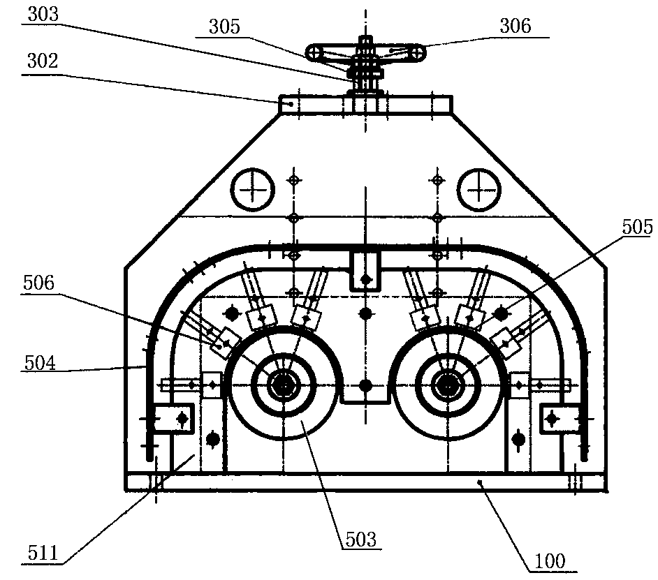
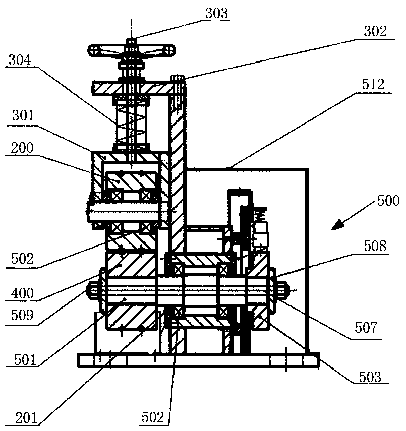
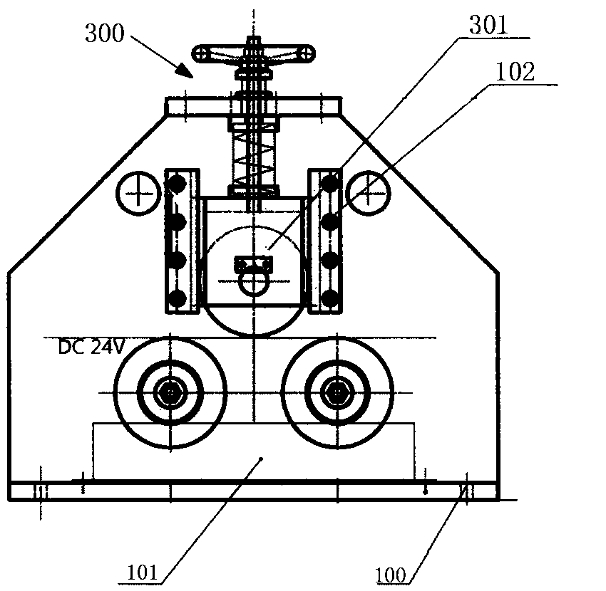
[0029] see Figure 1-Figure 3 , a cathode roller machine of the present invention, comprising a headstock 100, an upper roller 200, a lower roller 400 and a carbon brush assembly 500, the upper roller 200 is arranged on the headstock 100, and the upper roller 200 and the machine An adjustment assembly 300 is arranged between the headstocks 100, and the adjustment assembly 300 drives the upper roller 200 to move; the two lower rollers 400 are arranged on the headstock 100, and the two lower rollers 400 are connected to the The upper roller 200 is arranged in a triangle; the carbon brush assembly 500 is arranged corresponding to the lower rolle...


PUM


Abstract

The invention belongs to the technical field of steel wire production. A cathode roller machine comprises a machine head base; an upper roller is arranged on the machine head base, and an adjusting assembly is arranged between the upper roller and the machine head base, and drives the upper roller to act; two lower rollers are arranged on the machine head base, and the two lower rollers and the upper roller are triangularly arranged; carbon brush assemblies and the lower rollers are correspondingly arranged; each carbon brush assembly comprises a lower roller shaft; the middle portions of thelower roller shafts are arranged on the machine head base through bearings, and each lower roller is fixedly arranged at one end of the corresponding lower roller shaft; conductive sliding rings are fixedly arranged at the other ends of the lower roller shafts; and conductive copper bars are arranged on the machine head base in a supporting manner. The cathode roller machine is reasonable in structural design, stability is greatly improved, the heating amount can be effectively lowered, and the problems that the using performance of the bearings is lowered and the service life is shortened under the conductive situation can also be solved.

Description

technical field [0001] The invention belongs to the technical field of steel wire production, and in particular relates to a cathode roller machine. Background technique [0002] Phosphating is a commonly used pretreatment technology. In principle, it should belong to chemical conversion film treatment. It is mainly used for phosphating on the surface of steel, and non-ferrous metals (such as aluminum and zinc) can also be phosphating. Phosphating is a process in which chemical and electrochemical reactions form a phosphate chemical conversion film, and the formed phosphate conversion film is called a phosphating film. The purpose of phosphating is mainly to provide protection for the base metal and prevent the metal from being corroded to a certain extent; it is used as a primer before painting to improve the adhesion and anti-corrosion ability of the paint film layer; it can reduce friction in the metal cold processing process Lubrication. [0003] In the process of phos...

Claims


Application Information

Patent Timeline
IPC IPC(8): C25D11/36C25D17/12C25D7/06
CPCC25D7/0607C25D11/005C25D11/36C25D17/12
Inventor 王月琴刘二峰
Owner 河南恒星钢缆股份有限公司
Why Eureka
Try Eureka