
Flue gas waste heat recovery and heat exchange system

A heat exchange system and flue gas waste heat technology, applied in indirect heat exchangers, heat exchanger types, climate sustainability, etc., can solve the problems of low energy efficiency ratio of flue gas heat energy recovery, achieve simple measurement and ensure detection accuracy , the effect of high automation efficiency

Pending Publication Date: 2019-03-26
启明星宇节能科技股份有限公司
View PDF7 Cites 1 Cited by
  • Summary
  • Abstract
  • Description
  • Claims
  • Application Information

AI Technical Summary

Problems solved by technology

[0007] Therefore, the present invention provides a flue gas waste heat recovery heat exchange system to overcome the problem of low energy efficiency ratio of flue gas heat energy recovery in the prior art

Method used


Image

  • Flue gas waste heat recovery and heat exchange system
  • Flue gas waste heat recovery and heat exchange system
  • Flue gas waste heat recovery and heat exchange system

Examples


Embodiment 1

[0056] In this example, the above-mentioned system will be used to exchange heat for the flue gas, in which 100 tons of flue gas is used for heat exchange, the exhaust gas temperature is 90°C, the heat exchange is 35°C, the heat exchange temperature difference is 90-35=55°C, and the flue gas quality is 1.256 kg / m 3 , 100 boilers discharge 200,000-250,000 m of flue gas per hour 3 / h, this embodiment takes an average of 225,000 m 3 / h calculation; circulation pump flow:

[0057] Q=cm(t2-t1)

[0058] 1398870 joules=4.2*1000*m*55

[0059] m=1398870 joules / 4.2*1000*5

[0060] =66.6*24=1598*2 safety factor=3196t

[0061] Circulation pump flow: 3196 / 24=133 tons.

[0062] Calculate according to Q=cm(t2-t1), where Q is the total heat of the flue gas; C is the specific heat capacity of the flue gas, and the specific heat capacity of the flue gas at 100°C is C=1; m is the mass of the flue gas; t2 is the inlet temperature of the flue gas; t1 is the flue gas discharge temperature. ...


PUM


Abstract

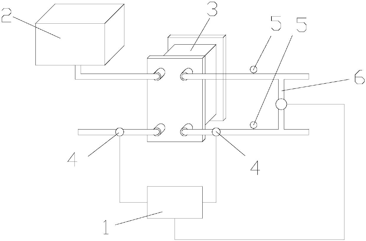
The invention relates to a flue gas waste heat recovery and heat exchange system which perform heat exchange on waste heat water and heat supply water to recover waste heat in flue gas and reach efficient heat exchange on water. The flue gas waste heat recovery and heat exchange system comprises a control unit, a water tank used for storing the waste heat water, a waste heat exchange device and acirculation pump; the control unit is arranged outside a pipeline, is used for controlling the pipeline and can perform detection on a detection difference before and after heat exchange on heat supply water in the pipeline and controls the pipeline to reach a corresponding state after the pipeline starts to run; the waste heat exchange device is connected with the water tank and is used for performing heat exchange on the waste heat water and the heat supply water; and the circulation pump is connected with the waste heat exchange device and is sued for controlling a circulation pump for running of the waste heat water and the heat supply water in the pipeline. The flue gas waste heat recovery and heat exchange system uses the waste heat to cool flue gas when the flue gas is not treated,can reach the maximum heat exchange efficiency, performs heat exchange on the waste heat water and the heat supply water without causing dangers due to leakage at the same time, lowers the safety hidden dangers in the system and is high in recovery energy efficiency ratio.

Description

technical field [0001] The invention relates to the technical field of fluid heat exchange, in particular to a flue gas waste heat recovery heat exchange system. Background technique [0002] The existing gas-fired heating boiler flue gas waste heat recovery system adopts a conventional flue gas waste heat recovery device. The boiler return water enters the flue gas waste heat recovery device first, absorbs the heat of the flue gas, and then enters the boiler to continue the temperature rise until it reaches the required temperature for heating. to the user; the flue gas temperature drops from 160-210°C to 110°C and then discharged to the atmosphere; although the flue gas waste heat recovery device is used at present, it only absorbs a small part of the heat in the flue gas, and most of the heat (including water The latent heat of vaporization in the steam and the heat in the flue gas) are still wasted. That is, a large amount of flue gas is discharged into the atmosphere, ...

Claims


Application Information

Patent Timeline
Patent Type & Authority Applications(China)
IPC IPC(8): F28D9/00F23J15/06
CPCF23J15/06F28D9/00Y02E20/30
Inventor 张久明
Owner 启明星宇节能科技股份有限公司
Learn More