
Sensor for measuring ice layer thickness

A technology of ice layer thickness and sensor, which is applied in the field of sensors, can solve the problems of difficult installation, measurement error, and inability to measure ice thickness, etc., and achieves the effects of low price, easy production, and avoiding ice layer damage or loose contact

Inactive Publication Date: 2019-03-26
SICHUAN UNIV
View PDF7 Cites 4 Cited by
  • Summary
  • Abstract
  • Description
  • Claims
  • Application Information

AI Technical Summary

Problems solved by technology

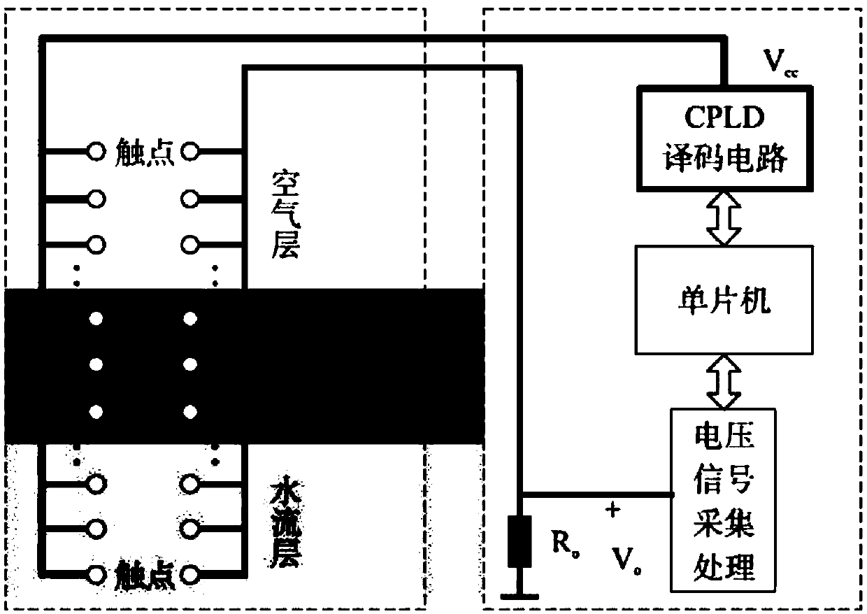
[0011] (2) The exposed contact sensor reduces its field applicability
Since the medium needs to communicate with the circuit at the contact point, the sensor circuit must be exposed. Therefore, in order to improve the measurement accuracy, the metal conductor at the contact point must be thin enough. In the field environment, especially in the cold environment, it is easy to break the wire (Li Xinyu, 2006); at the same time, the exposed thin contact circuit is also susceptible to displacement due to the expansion and contraction of the ice layer, which will cause errors in the measurement results
[0012] (3) Not easy to install
It can be clearly seen that the water under the ice layer submerges the sensor through the installation hole. At this time, on the one hand, the sensor is surrounded by water, and the ice thickness cannot be measured, and it is necessary to wait for the water to refreeze; There is also a difference in thickness
[0013] (4) The complex control system increases the uncertainty of field use
[0018] (2) Not easy to install
Although the capacitive sensing sensor avoids the shortcomings of the exposed contact points of the resistive sensor, the polar plate still needs to be fixed and wrapped with insulating materials, and it is also difficult to install directly. It is necessary to use an electric drill to drill installation holes on the ice, such as figure 2 shown
[0019] It can be clearly seen that the water under the ice layer submerges the sensor through the installation hole. At this time, on the one hand, the sensor is surrounded by water, and the ice thickness cannot be measured, and it is necessary to wait for the water to refreeze; There is also a difference in thickness
[0020] (3) The complex control system increases the uncertainty of field use
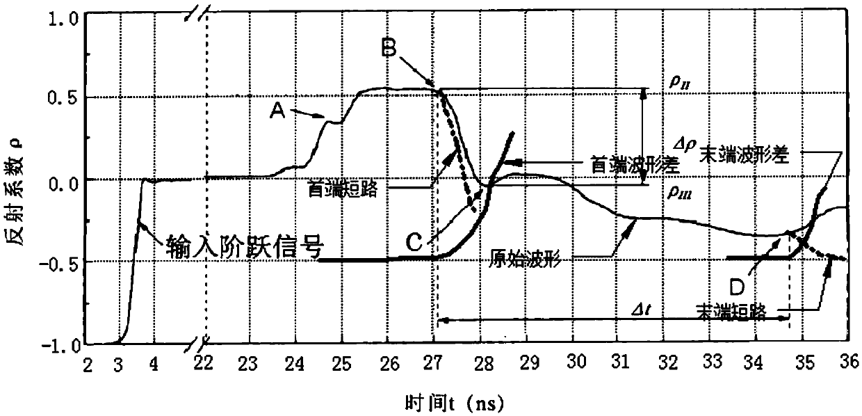
Through the time difference Δt between point B and point D of the waveform, that is, the propagation time of the electromagnetic wave in the medium, the propagation speed of the electromagnetic wave in the medium can be obtained, which is: where L is the length of the probe inserted into the medium, the medium constant: To measure ice thickness by TDR, it is necessary to measure the propagation time on the premise of knowing the dielectric constant of the ice layer to obtain the ice thickness. thick, contradictory

Method used


Image

  • Sensor for measuring ice layer thickness
  • Sensor for measuring ice layer thickness
  • Sensor for measuring ice layer thickness

Examples


Embodiment Construction

[0047] In order to make the purpose, technical solutions and advantages of the present invention clearer, the following technical solutions in the present invention are clearly and completely described. Obviously, the described embodiments are some embodiments of the present invention, rather than all embodiments. Based on the embodiments of the present invention, all other embodiments obtained by persons of ordinary skill in the art without creative efforts fall within the protection scope of the present invention.

[0048] Such as Figure 1-5 Shown, a kind of in-situ measuring sensor of ice layer thickness of the present invention comprises

[0049] Stainless steel sleeve 1, one end is 1cm away from the top, and a single side opening 7 with a width of 0.5cm is opened to allow air to enter, which not only reduces the pressure to facilitate drilling, but also forms an ice-air interface;

[0050] The stainless steel probe 2 is installed in the center of the stainless steel sle...


PUM


Abstract

The invention provides a sensor for measuring an ice layer thickness in an in-situ mode. The sensor comprises a stainless steel sleeve. The inner diameter of the stainless steel sleeve is 4.5cm, a length is 30cm. A single side opening with the width of 0.5cm, which has a 1cm distance with a top, passes through a bottom. The wall thickness of the sleeve is 0.2cm. The external portion of a top end is provided with a pipe thread which can be rotatably connected to an electric drill. The bottom is equipped with teeth. The center of the sleeve is provided with a stainless steel needle with the diameter of 0.5cm and a length is 30cm. The top is fixed through an epoxy resin and is isolated from the sleeve. The top end of the sleeve is provided with a BNC joint so that the sleeve and the externallayer metal net of a coaxial cable are connected, and a probe and the center metal wire of the coaxial cable are connected. In the invention, a price is low, a precision instrument in a resistive andcapacitive sensor is not needed so that the sensor is easy to produce and apply.

Description

technical field [0001] The invention belongs to the technical field of sensors, in particular to a sensor for measuring the thickness of an ice layer. Background technique [0002] Realizing continuous automatic monitoring of the thickness of ice layers in reservoirs, rivers, lakes, oceans, glaciers, etc. , under unfavorable working conditions such as inconvenient transportation and power supply, and harsh climate and environment. Therefore, a high-precision automatic monitoring method and device that can be adapted to reflect the internal changes of the ice layer under field environmental conditions is of great practical value. [0003] At present, the methods of measuring the thickness of ice and snow at home and abroad can be summarized into three types: [0004] (1) Relying on the emitted electromagnetic waves, sound waves, etc. to penetrate the ice layer, and use the time it takes to return to the receiver to convert the thickness of ice and snow. Sea ice monitoring ...

Claims


Application Information

Patent Timeline
Patent Type & Authority Applications(China)
IPC IPC(8): G01B7/06
CPCG01B7/102
Inventor 谭霄刘超李乃稳庄文化贺宇欣
Owner SICHUAN UNIV
Learn More