A frequency modulation transmitter

A technology of FM transmission and frequency offset, applied in FM carrier system, power oscillator, automatic power control, etc., can solve problems such as inability to ensure frequency stability and accuracy, slow FM source locking speed, and reduced loop locking bandwidth. , to avoid opening the cover circuit adjustment or reprogramming, flexible frequency and frequency offset settings, frequency stability

Active Publication Date: 2020-09-25
HUBEI SANJIANG SPACE XIANFENG ELECTRONICS&INFORMATION CO LTD
View PDF4 Cites 0 Cited by
  • Summary
  • Abstract
  • Description
  • Claims
  • Application Information

AI Technical Summary

Problems solved by technology

Phase-locked frequency modulation technology mainly includes single-point injection type phase-locked frequency modulation and two-point injection type phase-locked frequency modulation. The structure of single-point injection type phase-locked frequency modulation is relatively simple, which includes voltage-controlled Reference source, phase detector, loop filter, input pre-adjustment circuit, the modulation signal is directly loaded on the input end of the voltage-controlled oscillator after pre-adjustment and shaping, so that the output frequency of the voltage-controlled oscillator changes linearly with the modulation signal. Its modulation characteristics are related to the loop bandwidth. In order to meet the modulation requirements, the loop bandwidth is usually designed to be low, resulting in a reduction in the loop locking bandwidth, resulting in a slow locking speed of the FM source and loss of lock. Therefore, it is only suitable for low bit rate signals. Modulation; the two-point injection phase-locked frequency modulation structure is relatively complex, including a voltage-controlled oscillator, a frequency divider link, a crystal oscillator reference source, a phase modulator, a phase detector, a loop filter, an input preset circuit, and an integrator circuit, which divides the telemetry PCM signal into two paths, one path is injected into the voltage-controlled oscillator, so that the output frequency of the voltage-controlled oscillator changes linearly with the modulating signal, and the other path is injected into the integrator to perform phase modulation with the output signal of the crystal oscillator reference source. Its phase-modulated output signal is also used as a phase-locked reference source for phase-locked, and broadband frequency modulation is performed on the crystal oscillator. At the same time, the frequency stability of the output signal must be satisfied, which is difficult to debug. Therefore, it is difficult to debug when working at a high bit rate. Ensure frequency stability and accuracy and poor spurious suppression

Method used


Image

  • A frequency modulation transmitter

Examples


Embodiment Construction

[0024] In order to make the object, technical solution and advantages of the present invention clearer, the present invention will be further described in detail below in conjunction with the accompanying drawings and embodiments. It should be understood that the specific embodiments described here are only used to explain the present invention, not to limit the present invention.

[0025] In addition, the technical features involved in the various embodiments of the present invention described below can be combined with each other as long as they do not constitute a conflict with each other. The present invention will be further described in detail below in combination with specific embodiments.

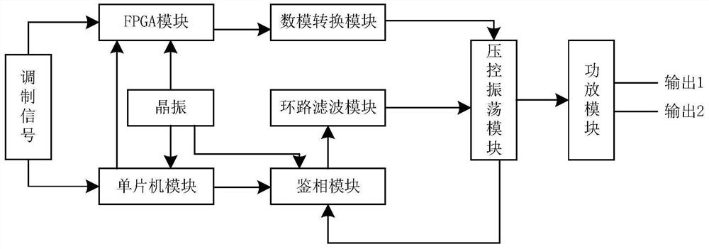
[0026] figure 1 It is a structural schematic diagram of an FM transmitting device in a preferred embodiment of the present invention. like figure 1 As shown, the device includes a single-chip microcomputer module, an FPGA module, an analog-to-digital conversion module, a phase de...


PUM


Abstract

The invention discloses a frequency modulation transmitting device. The device comprises a single-chip microcomputer module, an FPGA module, an analog-to-digital conversion module, a phase discrimination module, a loop filtering module and a voltage controlled oscillation module. The single-chip microcomputer module performs frequency setting on the phase discrimination module according to a preset working mode to adjust the input voltage of the phase discrimination module acting on the coarse tuning end of the voltage controlled oscillation module, so that the output signal of the voltage controlled oscillation module is the same as the setting value of the phase discrimination module. The FPGA module performs high-speed sampling on the received external data signals and controls the input voltage of the digital-to-analog conversion module according to the frequency offset control word of the code rate corresponding to the received external data signal. The digital-to-analog conversion module controls the input voltage of the digital conversion module acting on the fine tuning end of the voltage controlled oscillation module according to the current input voltage, so that the precision of the output signal of the voltage controlled oscillation module reaches a preset value. According to the frequency modulation transmitting device, coarse tuning and fine tuning of the output signal of the voltage controlled oscillation module is realized, and the effects that the output signal frequency of the transmitting device is stable, the spectrum purity is high, and the resonance clutter suppression degree is high are achieved.

Description

technical field [0001] The invention belongs to the field of antennas, and in particular relates to a frequency modulation transmitting device. Background technique [0002] The FM transmitting device is used to modulate the audio signal and the high-frequency carrier into a FM wave, so that the frequency of the high-frequency carrier changes with the audio signal, and then amplifies the generated high-frequency signal, excites it, power amplifiers and a series of impedance matching, A device that causes a signal to be output to an antenna for transmission. As a simple communication tool, the FM transmitting device can carry out effective mobile communication without a transfer station, because it is widely used in small-scale mobile communication projects in the fields of production, security, and field engineering. [0003] With the development of phase-locking technology, frequency modulation technology, new technology and new devices, the FM transmitting device directly...

Claims


Application Information

Patent Timeline
Patent Type & Authority Patents(China)
IPC IPC(8): H04B1/04H04L27/12H03L7/099H03B5/04
CPCH03B5/04H03L7/0995H04B1/04H04L27/12
Inventor 祝锐齐开佳高帆
Owner HUBEI SANJIANG SPACE XIANFENG ELECTRONICS&INFORMATION CO LTD
Why Eureka
Try Eureka