Automatic punching device and assembly line process thereof

A stamping device and automatic technology, applied in the field of stamping processing, can solve problems such as low efficiency, achieve the effects of easy operation, saving labor costs, and ensuring quality

Inactive Publication Date: 2019-03-29
珠海科特文工艺品制造有限公司
View PDF5 Cites 5 Cited by
  • Summary
  • Abstract
  • Description
  • Claims
  • Application Information

AI Technical Summary

Problems solved by technology

[0003] The purpose of the present invention is to provide an automatic stamping device and its assembly line process. By providing a material feeding transmission panel and a feeding installation plate, the servo motor can push the plates stored in the material storage shell to the material feeding transmission panel for transmission. , when the plate is transported between the stamping device and the feeding installation plate, the first electric push rod works to push the push plate to push the plate from the material distribution panel to the inside of the stamping device, which can replace manual stamping and handling of materials at each stamping station , loading and unloading, etc., saving manpower and labor costs, improving labor and equipment safety, to solve the problem of stamping, manually put the plate into the stamping device, and after the plate is stamped and formed by the stamping device, the finished product is manually released from the stamping device The problem of inefficiency in taking out

Method used


Image

  • Automatic punching device and assembly line process thereof
  • Automatic punching device and assembly line process thereof
  • Automatic punching device and assembly line process thereof

Examples


Embodiment 1

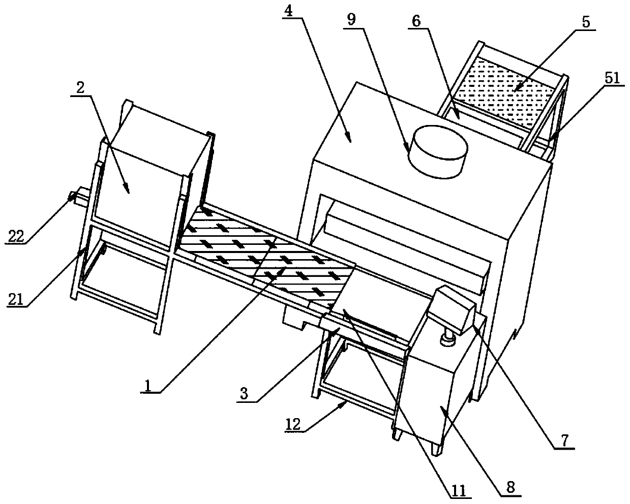
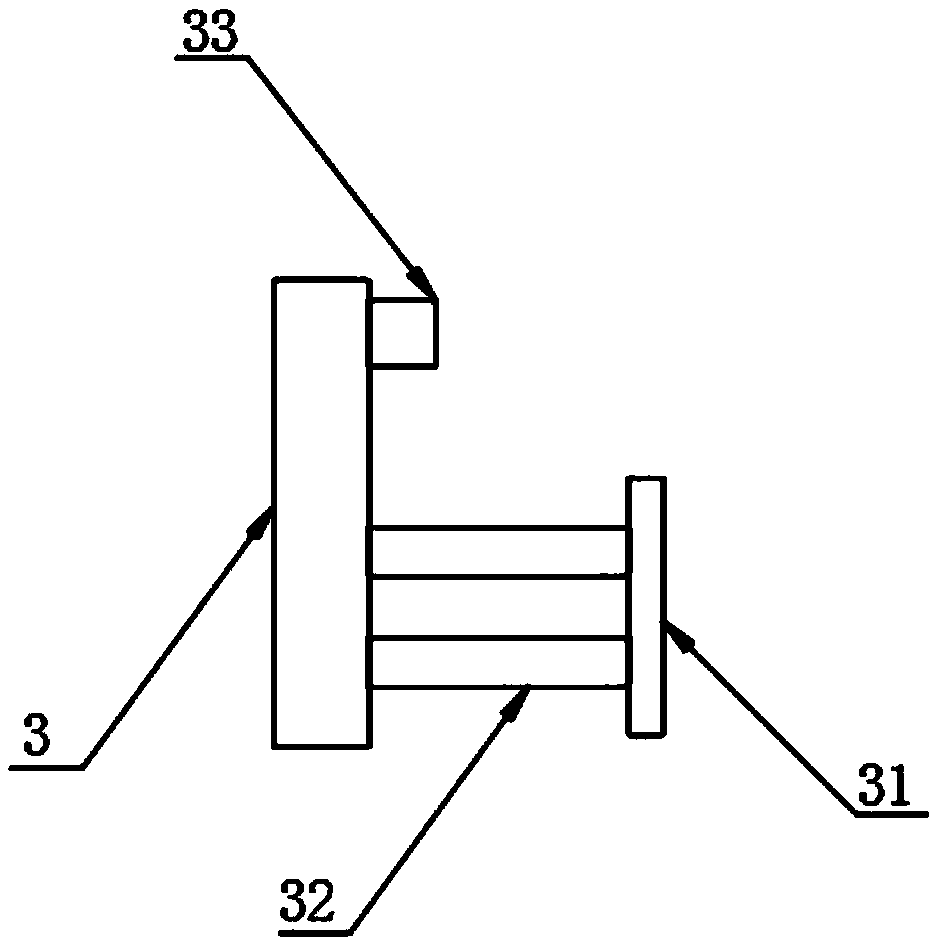
[0028] The present invention provides Figure 1-4 The automatic punching device and its assembly line process shown include an input transmission panel 1. One side of the input transmission panel 1 is provided with a storage housing 2, and one end of the input transmission panel 1 is provided with a front side surface Feeding mounting plate 3, the input transmission panel 1 is provided with a stamping device 4 on the rear side of one end. The stamping device 4 includes a stamping housing 41, a stamping panel 42, a stamping bottom plate 43, a stamping top plate 44, a laser sensor 45, and a hydraulic cylinder 46. ​​The hydraulic rod 47, the hydraulic motor 48 and the supporting seat 49. The punching device 4 is provided with a discharge transmission panel 5 on the outside, the top of the discharge transmission panel 5 is provided with a top plate 6, and the feeding transmission panel 1 side A control device 7 is provided, a support housing 8 is provided at the bottom of the contr...

Embodiment 2

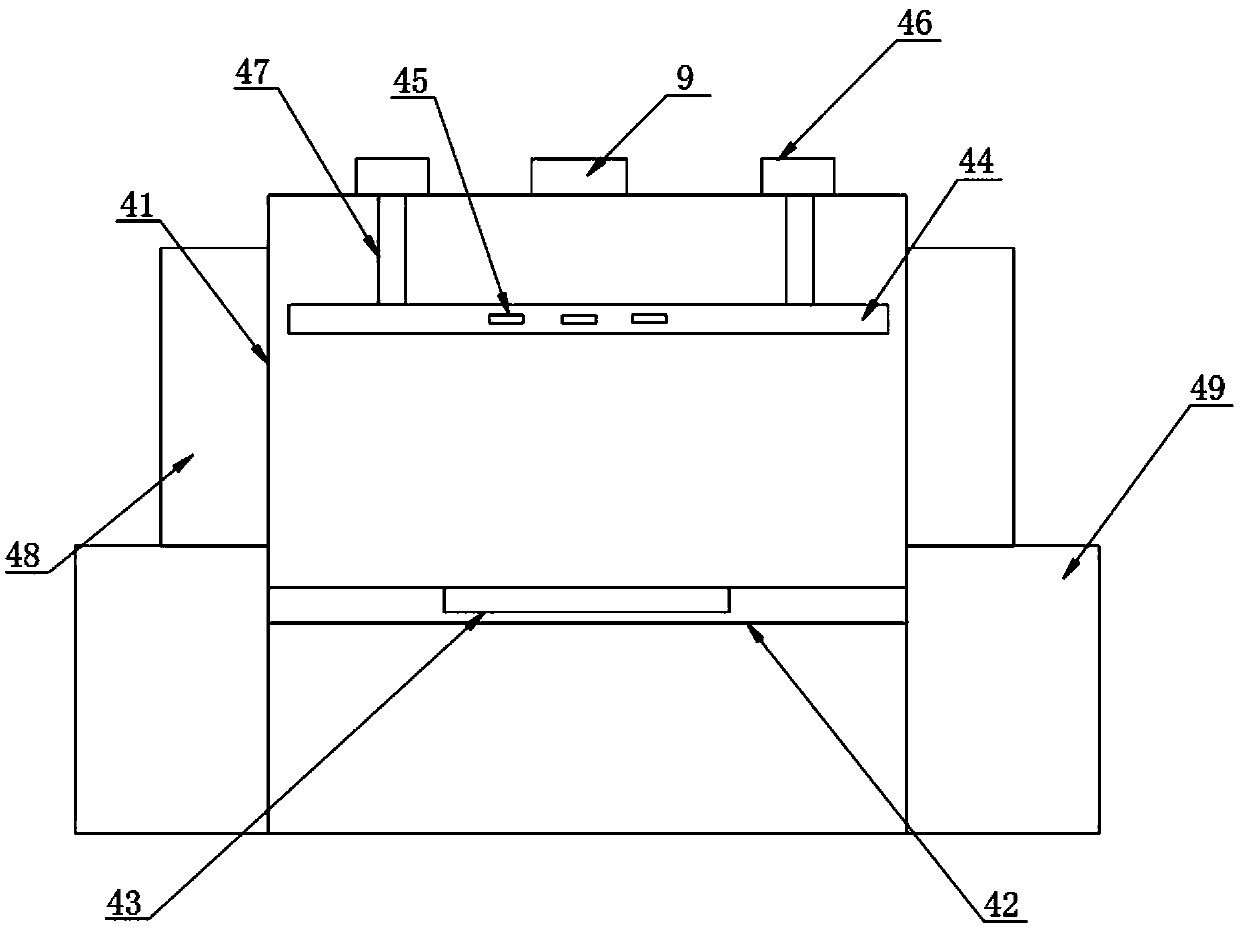
[0034] The punching shell 41 is hollow, and the punching shell 41 is provided with a punching panel 42 inside, and the punching panel 42 is connected to the feed transmission panel 1, and the punching panel 42 is provided with a punching bottom plate 43. The top of the stamping panel 42 is provided with a stamping top plate 44, the front and rear surfaces of the stamping top plate 44 are evenly provided with laser sensors 45, the top of the stamping housing 41 is provided with a hydraulic cylinder 46, the stamping top plate 44 and the hydraulic cylinder 46 A hydraulic rod 47 is provided therebetween, and the hydraulic rod 47 is in transmission connection with the hydraulic cylinder 46. A hydraulic motor 48 is provided on the outer side of the stamping housing 41. 48 is provided with a support base 49 at the bottom.

[0035] The beneficial effects of this embodiment: the material enters the stamping panel 42 in the stamping shell 41, the laser sensor 45 detects the type of the she...

Embodiment 3

[0037] The bottom of the discharging transmission panel 5 is provided with a discharging support frame 51, and the discharging transmission panel 5 is fixedly connected with the punching panel 42.

[0038] The top plate 6 is arranged outside the punching device 4, the bottom of the top plate 6 is evenly provided with a camera 61, one end of the 6 is provided with a hair dryer 62, and the bottom of the hair dryer 62 is connected with a blowing nozzle 63.

[0039] The control device 7 includes a PLC controller, a wireless data transmission module, a data processing module, and a data storage module. The control device 7 is provided with a touch screen on the surface, and the control device 7 is connected to the buzzer 9 through a transmission cable. And control the buzzer 9.

[0040] The beneficial effects of this embodiment: the punched sheet enters the discharge transmission panel 5 from the punching housing 41, and the camera 61 captures the size and model of the punched sheet and t...


PUM


Abstract

The invention discloses an automatic punching device. The automatic punching device comprises a feeding conveying panel; a material storage shell is arranged on one side of the feeding conveying panel; a feeding mounting plate is arranged on the surface of the front side of the feeding conveying panel; the rear side of one end of the feeding conveying panel is provided with a punching device body;the punching device body comprises a punching shell, a punching panel, a punching bottom plate, a punching top plate, a laser sensor, a hydraulic cylinder, a hydraulic rod, a hydraulic motor and a support base; and a discharging conveying panel is arranged on the outer side of the punching device body. By arranging the feeding conveying panel and the feeding mounting plate, plates stored in the material storage shell can be pushed onto the feeding conveying panel for conveying by starting a servo motor, when the plates are conveyed between the punching device body and the feeding mounting plate, a push plate is pushed by operating a first electric push rod to push the plates from a material distribution panel into the punching device body, manual operations such as material punching, conveying, feeding and discharging on all punching stations can be replaced, and the labor cost is reduced.

Description

Technical field [0001] The invention relates to the technical field of stamping processing, in particular to an automatic stamping device and its assembly line process. Background technique [0002] The punching machine is one of the common machining equipment, and the punching machine can be used for mass production of mechanical structures or components. The punching machine uses a mold to process the plate to deform or break the plate, thereby forming a finished product of the desired shape. Existing stamping machines generally include a frame and a stamping device set on the frame. During stamping, the sheet is manually placed into the stamping device. After the sheet is stamped and formed by the stamping device, the finished product is manually removed from the stamping device Taking out is inefficient. Therefore, it is necessary to invent an automatic stamping device and its assembly line process to solve the above problems. Summary of the invention [0003] The purpose of...

Claims


Application Information

Patent Timeline
Patent Type & Authority Applications(China)
IPC IPC(8): B21D22/02B21D43/02B21D55/00B21C51/00B08B5/02
CPCB08B5/02B21C51/00B21D22/02B21D43/027B21D55/00
Inventor 何涌戴丽何欣儒
Owner 珠海科特文工艺品制造有限公司
Why Eureka
Try Eureka