
Motor steering transmission system for full-revolving propulsor

A technology of azimuth propeller and transmission system, which is applied in the field of motor rudder drive system for azimuth propeller, can solve problems such as easy vibration and deformation, end face runout, and radial runout are too large, so as to reduce support strength and Carrying load, preventing damage, and strong stability

Inactive Publication Date: 2019-03-29
合肥倍豪海洋装备技术有限公司
View PDF6 Cites 3 Cited by
  • Summary
  • Abstract
  • Description
  • Claims
  • Application Information

AI Technical Summary

Problems solved by technology

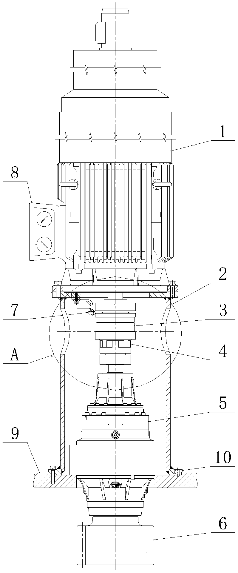
[0003] As the power of the rudder motor increases, the size and weight also increase. If the reduction gear box is still used to support the entire motor, the rigidity of the entire structure is somewhat insufficient. When the motor is running, vibration and deformation are likely to occur, and even lead to zero. Parts are damaged. Secondly, the traditional motor rudder transmission system does not adopt a certain structure to protect the entire rudder system. If the blade hits some objects underwater, causing the rudder angle to be forced to rotate, then the entire rudder In the system, the most fragile part will be damaged, and the replacement and maintenance of parts will affect the normal operation of the ship. In addition, with the increase in the size of the steering motor and reduction gearbox, the size deviation and shape of a single part will The position deviation will also increase. When installing parts, the accumulation of deviation will cause the end face runout and radial runout between the two parts to be too large, which will affect the stable operation of the equipment. In severe cases, the parts will be damaged. In order to solve the above problems , a motor rudder drive system for azimuth thrusters is proposed

Method used


Image

  • Motor steering transmission system for full-revolving propulsor
  • Motor steering transmission system for full-revolving propulsor
  • Motor steering transmission system for full-revolving propulsor

Examples


Embodiment Construction

[0022] The technical solutions in the embodiments of the present invention will be clearly and completely described below in conjunction with the embodiments of the present invention. Apparently, the described embodiments are only some of the embodiments of the present invention, not all of them. Based on the embodiments of the present invention, all other embodiments obtained by persons of ordinary skill in the art without creative efforts fall within the protection scope of the present invention.

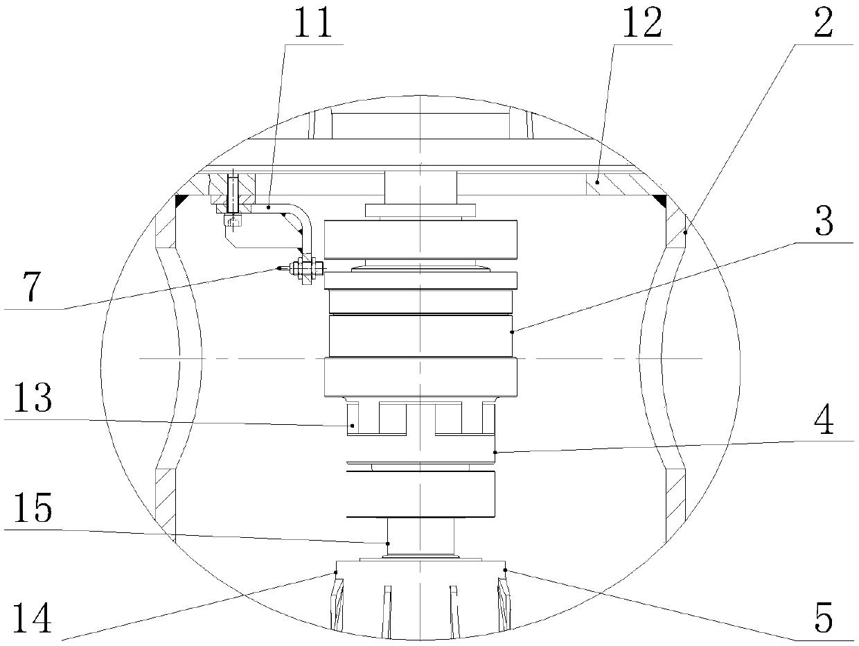
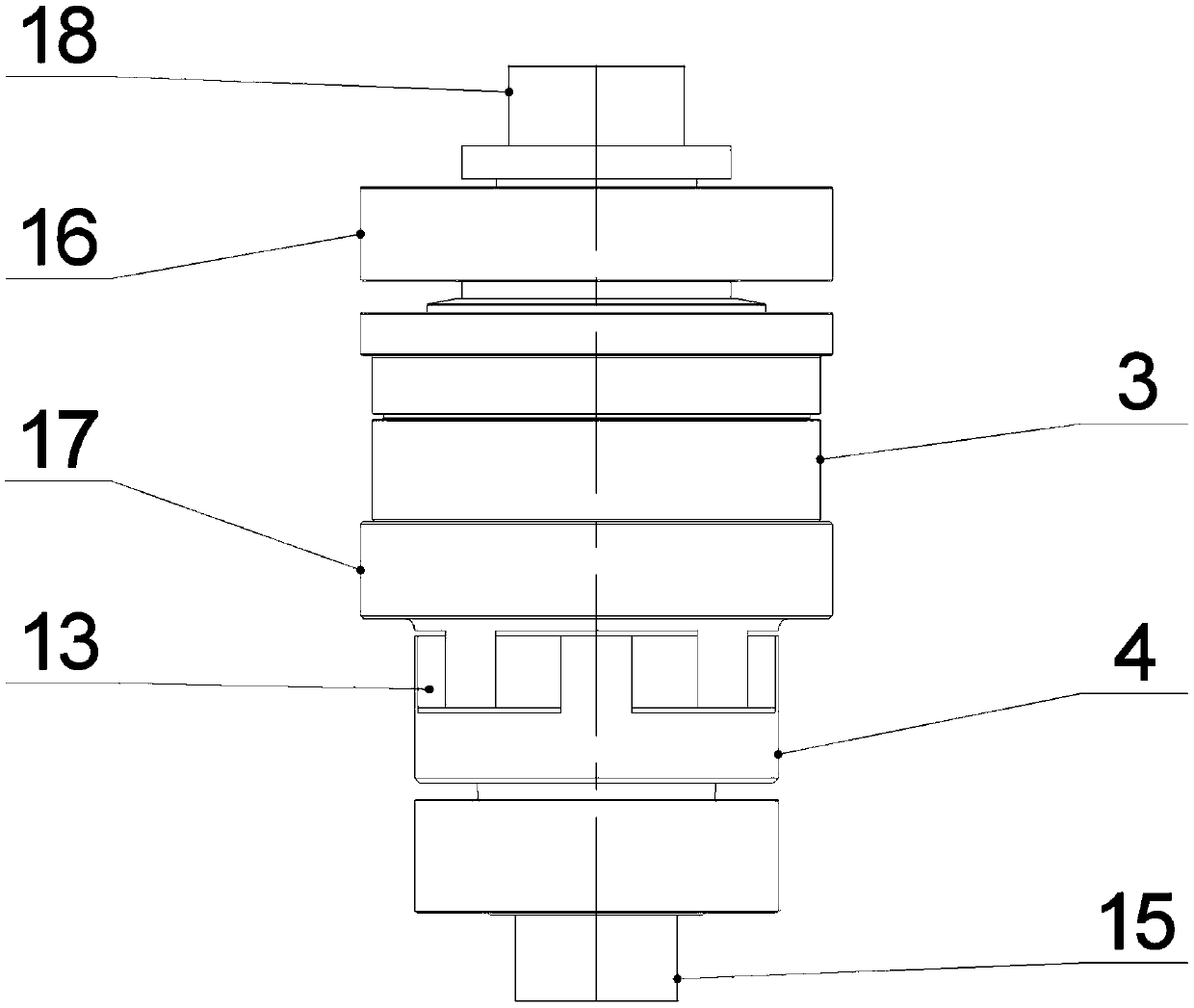
[0023] like Figure 1-3 As shown, a motor steering rudder transmission system for an azimuth propeller includes a steering motor bracket 2, a horizontal plate 12 and a mounting flange 10, and the two ends of the steering motor bracket 2 are installed through the horizontal plate 12. The flange 10 is fixedly installed, the upper surface of the horizontal plate 12 at the upper end is fixedly equipped with a rudder motor 1, and the bottom surface of the mounting flange 10 at the bott...


PUM


Abstract

The invention discloses a motor steering transmission system for a full-revolving propulsor. The motor steering transmission system comprises a steering motor bracket, transverse plates and a mountingflange, wherein two ends of the steering motor bracket are fixedly installed through matching of two sets of parallel transverse plates and the mounting flanges, the upper end surface of the transverse plate at the upper end is fixedly mounted with a steering motor, and the bottom end surface of the mounting flange at the bottom end is provided with a rotary propeller. The steering motor of the motor steering transmission system for the full-revolving propulsor is supported by an independent steering motor bracket, so that the rigidity of the whole system is increased, and the support strength of a speed-reducing gear box is reduced. When the steering transmission system encounters a large external force, a safe clutch can be automatically disengaged to play a protecting effect, a position sensor can provide an alarm indication, the reset operation of the safe clutch is very simple, consumes short time and has little impact on the operation of a ship, the elastic coupler can bear larger end face runout and radial runout between the steering motor and the speed-reducing gear box.

Description

technical field [0001] The invention belongs to the technical field of shafting transmission, and more specifically relates to a motor steering rudder transmission system for an azimuth thruster. Background technique [0002] With the development of my country's shipbuilding industry, high-power azimuth propellers for large ships have broad application prospects. As the power of the azimuth propeller increases, the power of the motor driving the rudder also increases. In the traditional motor rudder drive system, the general rudder motor has relatively small power, small size and light weight, and can be directly Connect the reduction gearbox, and then drive the slewing bearing to turn the rudder through the steering pinion, and the entire steering motor is supported by the reduction gearbox. [0003] As the power of the rudder motor increases, the size and weight also increase. If the reduction gear box is still used to support the entire motor, the rigidity of the entire ...

Claims


Application Information

Patent Timeline
Patent Type & Authority Applications(China)
IPC IPC(8): B63H25/20B63H25/52
CPCB63H25/20B63H25/52
Inventor 张方华张燕
Owner 合肥倍豪海洋装备技术有限公司
Learn More