Garbage drying treatment system and method

A processing system and technology for waste drying, applied in combustion methods, drying, dryers, etc., can solve the problems of reducing the area of ​​waste drying, shortening drying cycle, and long drying cycle, so as to shorten the waste The effect of drying cycle, shortening drying cycle and reducing drying cost

Active Publication Date: 2019-03-29
杭州正晖建设工程有限公司
View PDF8 Cites 3 Cited by
  • Summary
  • Abstract
  • Description
  • Claims
  • Application Information

AI Technical Summary

Problems solved by technology

[0003] The invention overcomes the shortcomings of long garbage drying cycle, large floor area and high cost, and provides a garbage drying treatment system and method, which can shorten the drying cycle, reduce the garbage drying floor area, and reduce the cost

Method used


Image

  • Garbage drying treatment system and method
  • Garbage drying treatment system and method
  • Garbage drying treatment system and method

Examples


Embodiment 1

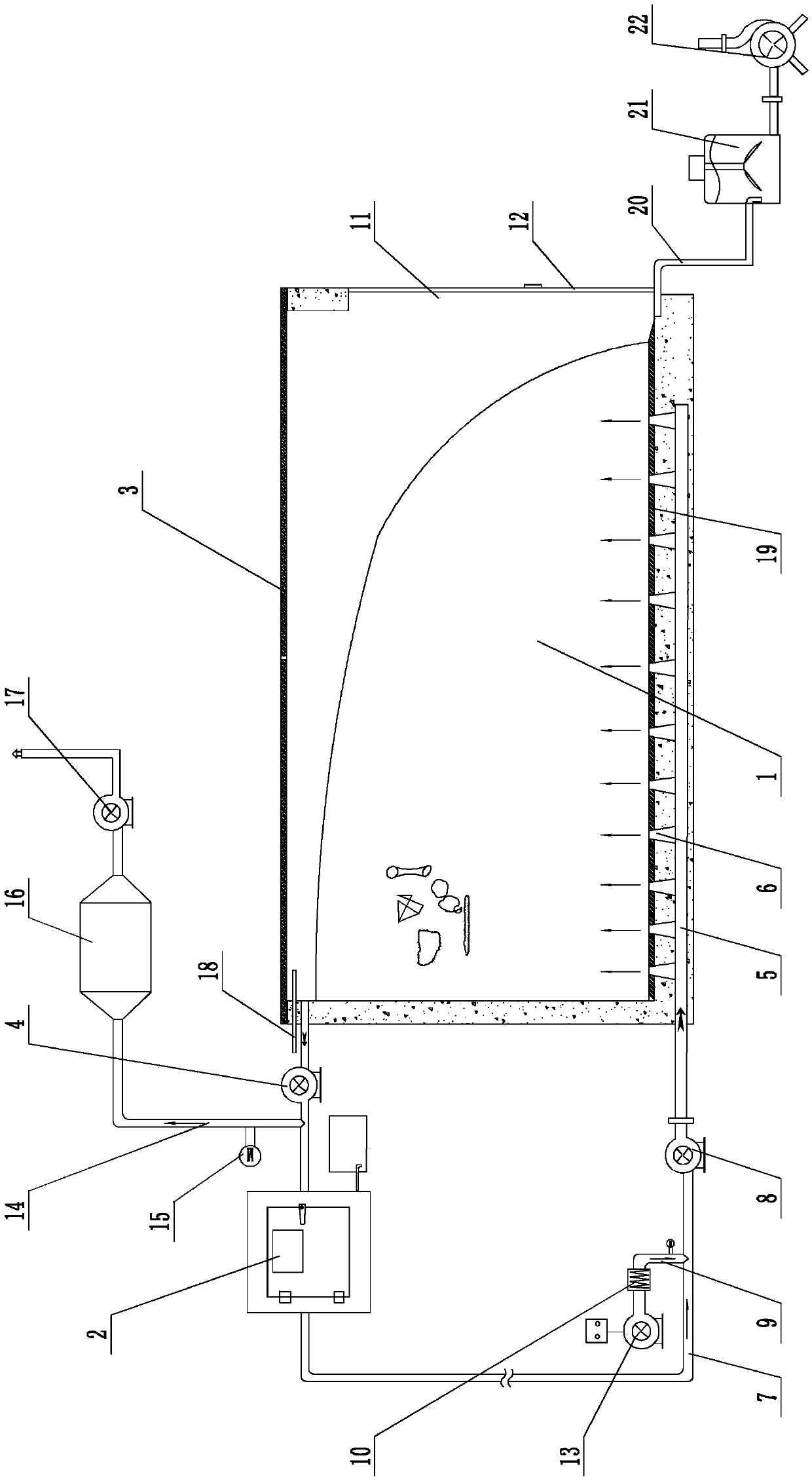
[0025] Embodiment 1: A kind of rubbish drying processing system (see attached figure 1 ), including drying bin 1, dehumidification heat pump 2, solar power generation panel 3 installed on the top of the drying bin to supply power to the entire garbage drying treatment system, a sealing ring is set between the solar power generation board and the top of the drying bin, and the solar power generation Connect the photovoltaic controller, battery, and inverter, and the current output by the inverter supplies power to the entire garbage drying treatment system. The position close to the upper end of the drying chamber is connected to the exhaust fan 4, and the dehumidification heat pump is connected to the exhaust fan. The ventilation pipe 5 is installed at the bottom of the drying chamber, and a number of ventilation nozzles 6 for spraying air into the drying chamber are installed on the ventilation pipe. Between the ventilation pipe and the dehumidification heat pump The hot air ...

Embodiment 2

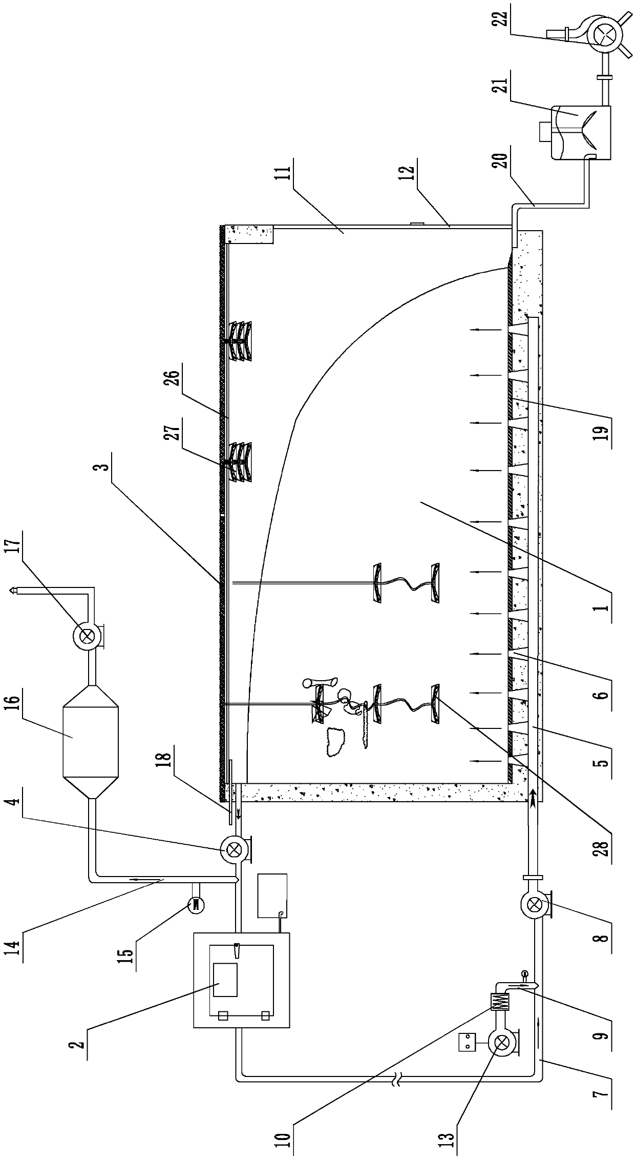
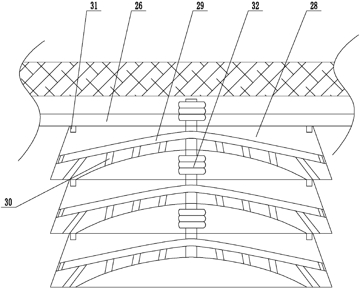
[0027] Embodiment 2: a kind of rubbish drying processing system (see attached figure 2 , attached image 3 ), its structure is similar to that of Embodiment 1, the main difference is that in this embodiment, a bracket 26 is installed near the upper end of the drying bin, and a number of ventilation assemblies 27 are installed on the bracket, and the ventilation assembly includes several ventilation cranes stacked up and down together. Block 28, ventilation cavity 29 is provided in the ventilation hanging block, the lower surface of the ventilation hanging block is a concave arc-shaped surface structure, and several ventilation holes 30 communicated with the ventilation cavity are provided on the lower surface and the side of the ventilation hanging block. The upper surface of the block is provided with several electromagnets 31 near the outer edge, and the adjacent two ventilation hanging blocks are attracted together by electromagnets. The ventilation hose 32 communicated w...

Embodiment 3

[0029] Embodiment 3: a kind of rubbish drying treatment system (see attached Figure 4 , attached Figure 5 ), its structure is similar to that of Embodiment 2, the main difference is that in this embodiment, the pressure plate 33 is hinged on both sides of the drying chamber near the door opening, the pressure plate is inclined upward toward the door opening, and the bottom of the drying chamber is installed between the pressure plate and the drying chamber. Positioning spring 34, an installation chamber 35 is provided at the bottom of the drying chamber close to the door opening, a driving gear 36 is installed in the installation chamber, lifting racks 37 are installed on the left and right sides of the chamber door, and the lower surface of the pressure plate near the upper end is movably connected to push the rack 38. The pushing rack and the lifting rack are respectively arranged on the left and right sides of the driving gear. Both the pushing rack and the lifting rack a...


PUM


Abstract

The invention discloses a garbage drying treatment system and method. The garbage drying treatment system and method aims to overcome the shortage of a long dry cycle, large area, and high cost. The garbage drying treatment system comprises a drying chamber and a dehumidifying heat pump, a solar panel for supplying power to the entire waste drying system is installed on top of the drying chamber,the position, near the top end, of the drying chamber communicates with a suction fan, the dehumidifying heat pump communicates with the suction fan, a ventilation duct is mounted at the bottom of thedrying chamber, a plurality of ventilation nozzles for injecting air into the drying chamber are mounted on the ventilation duct, a hot air pipe communicates between the ventilation duct and the dehumidifying heat pump, the hot air pipe is provided with a blower, a bypass pipe communicates between the blower on the hot air pipe and the dehumidifying heat pump, an electric heating wire is mountedin the bypass pipe, a door hole is formed in one side wall of the drying chamber, and a chamber door is sealed and mounted on the position of the door hole on the drying chamber.

Description

technical field [0001] The invention relates to a garbage treatment technology, more specifically, it relates to a garbage drying treatment system and method. Background technique [0002] With the rapid development of the domestic economy and the improvement of the consumption level of residents, the output of domestic garbage has increased year by year, and the harmless treatment of garbage has become one of the serious problems that plague the development of cities. Since domestic garbage is generally collected in a mixed manner, the garbage has high moisture content, low calorific value, complex components, and high organic matter content. The dry dehydration and resource classification of garbage, combined with incineration power generation, can quickly realize the harmless treatment of garbage and energy recovery and utilization. When incinerating garbage with high water content, the increase in moisture in the garbage consumes heat, which will lead to increased incin...

Claims


Application Information

Patent Timeline
Patent Type & Authority Applications(China)
IPC IPC(8): F23G5/04F23G5/44F26B21/00F26B25/00H02J7/35
CPCF23G5/04F23G5/44F26B21/001F26B25/00H02J7/35Y02P70/10
Inventor 苏海涛朱守兵张勇贾祎蔓代陈林陈勇刘涛姜志红柯卫良陈增丰杨华
Owner 杭州正晖建设工程有限公司
Why Eureka
Try Eureka