
High-temperature hot air device suitable for waste gas circulation heating of brick kiln

A waste gas circulation and hot air device technology, applied in waste heat treatment, furnace control devices, lighting and heating equipment, etc., can solve the problems of high investment cost, high maintenance cost, complex equipment, etc., achieve good adaptability, reduce energy consumption, The effect of improving the brick production rate

Pending Publication Date: 2019-03-29
NANCHANG INST OF TECH
View PDF0 Cites 4 Cited by
  • Summary
  • Abstract
  • Description
  • Claims
  • Application Information

AI Technical Summary

Problems solved by technology

[0003] At present, some brick kilns have begun to explore the way of using hot air to burn bricks, but either the equipment is complicated, the investment cost is high, and the maintenance cost is high; or it is difficult to control the temperature and the brick production rate is low.

Method used


Image

  • High-temperature hot air device suitable for waste gas circulation heating of brick kiln
  • High-temperature hot air device suitable for waste gas circulation heating of brick kiln
  • High-temperature hot air device suitable for waste gas circulation heating of brick kiln

Examples


Embodiment 1

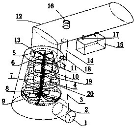
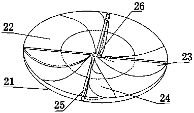
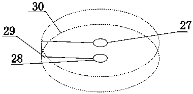
[0029] see Figure 1-9 , in an embodiment of the present invention, a high-temperature hot air device suitable for exhaust gas circulation heating of a brick kiln includes a hot air flow channel, a heater and an intelligent control system. The hot air flow channel includes a blower 1, an air inlet pipe 2, an outer cylinder 3 and The inner cylinder body 4 and the rotating body 19, the outer cylinder body 3 and the inner cylinder body 4 are all in the shape of a circular platform, the side wall of the outer cylinder body 3 is equipped with an air inlet pipe 2, and the other end of the air inlet pipe 2 is equipped with a blower 1, and The air duct 2 communicates with the outer cylinder 3, the inner cylinder 4 is installed inside the outer cylinder 3, the inner surface of the inner cylinder 4 is covered with heat insulating material, and an outer laminar flow is formed between the outer cylinder 3 and the inner cylinder 4 The cross-sectional area of ​​the outer flow channel is equ...

Embodiment 2

[0038] On the basis of Embodiment 1, a temperature-regulating pipe 14 is installed on the side wall of the outer cylinder 3, and the other end of the temperature-regulating pipe 14 communicates with the air outlet pipe 12. A temperature-regulating valve 18 is installed inside the temperature-regulating pipe 14. A pressure relief valve 16 is installed on the top of the air duct 12, and the control box 15 controls the blower 1 or the temperature regulating valve 18 to adjust the air temperature according to the measurement data of the temperature sensor 17. When the temperature is high, adjust the opening degree of the temperature regulating valve 18, draw cold air from the outer channel through the temperature regulating pipe 14 and send it to the air outlet pipe 12 to reduce the air temperature. When the pressure in the air outlet pipe 12 is too high, the pressure is released through the pressure relief valve 16 .


PUM


Abstract

The invention relates to the technical field of waste gas circulating heating devices, in particular to a high-temperature hot air device suitable for waste gas circulation heating of a brick kiln. The high-temperature hot air device comprises a hot air flow channel and a heater arranged in the hot air flow channel; the hot air flow channel comprises an air blower, an air inlet pipe, an outer cylinder body, an inner cylinder body and a rotating body, wherein the inner cylinder body is arranged in the outer cylinder body, an outer flow channel is formed between the outer cylinder body and the inner cylinder body, nozzles are evenly distributed on the top of the inner cylinder body, and the rotating body is arranged in the inner cylinder body. According to the high-temperature hot air devicesuitable for waste gas circulation heating of the brick kiln, the principle of fluid mechanics and aerodynamics is fully utilized, and an 80-degree inclined plane, a diffuser pipe heat flow channel,an impeller inner bottom plate flow mixing device, a four-leg supporting device and the like are adopted in the structure, so that not only is water contained in waste gas further removed, but also the waste gas is fully mixed in the heating area and keeps the long stagnation time, the waste gas is sufficiently heated, the heating efficiency is improved, and the energy consumption is reduced.

Description

technical field [0001] The invention relates to the technical field of waste gas circulation heating devices, more specifically, a high-temperature hot air device suitable for waste gas circulation heating of brick kilns. Background technique [0002] Coal heating methods commonly used in brick kilns, the frequency of coal addition, exhaust performance, heating uniformity, heating time and other factors affect each other in a complex manner. Even experienced technicians can hardly guarantee the brick production rate, and phenomena such as over-burning and under-burning often occur , At the same time, the energy consumption of the coal heating method is relatively large. my country has advocated energy saving and emission reduction in recent years, not only hoping to improve heating efficiency, but also requiring full use of brick kiln exhaust gas. [0003] At present, some brick kilns have begun to explore the method of using hot air to burn bricks, but either the equipment...

Claims


Application Information

Patent Timeline
Patent Type & Authority Applications(China)
IPC IPC(8): F27D99/00F27D17/00F27D19/00
CPCF27D17/00F27D19/00F27D99/0001F27D2019/0018F27D2099/0065Y02P10/25
Inventor 梁兴邓飞郭磊魏晓斌张松万志远温鑫婷
Owner NANCHANG INST OF TECH
Learn More