Concrete carbonization depth detection device

A carbonization depth and detection device technology, which is applied in the field of measurement and detection, can solve the problems of limited measurement depth, difficulty in controlling the size, and large damage to concrete components, and achieve the effect of large measurement depth and small damage

Pending Publication Date: 2019-03-29
重庆固力建筑工程质量检测有限公司
View PDF0 Cites 0 Cited by
  • Summary
  • Abstract
  • Description
  • Claims
  • Application Information

AI Technical Summary

Problems solved by technology

The problem is that it is troublesome to dig a hole, the shape of the hole is not standard and it is difficult to control the size, and the depth of its m

Method used


Image

  • Concrete carbonization depth detection device
  • Concrete carbonization depth detection device
  • Concrete carbonization depth detection device

Examples


Example Embodiment

[0023] The embodiments of the technical solution of the present invention will be described in detail below in conjunction with the accompanying drawings. The following embodiments are only used to illustrate the technical solutions of the present invention more clearly, and therefore are only used as examples, and cannot be used to limit the protection scope of the present invention.
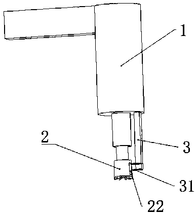
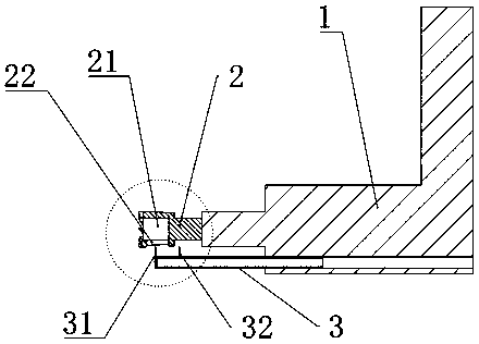
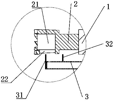
[0024] See Figure 1-7 , The present invention provides a concrete carbonization depth detection device, which includes a drill 1, a drill bit 2, and a reading ruler 3. The drill bit 2 is installed on the rotating shaft of the drilling rig 1, and the reading rule 3 is telescopically installed on the drilling rig 1. The reading ruler 3 is arranged in parallel with the drill bit 2. The drill bit 2 is provided with a central hole 21 in the center. The central hole 21 is cylindrical, and the central hole 21 penetrates the end of the drill bit 2 away from the drill 1, and the circumferential surface of...


PUM

PropertyMeasurementUnit
Lengthaaaaaaaaaa

Abstract

The invention discloses a concrete carbonization depth detection device. The device comprises a drilling machine, a drill bit and a reading ruler; the drill bit is mounted on a rotating shaft of the drilling machine; the reading ruler is telescopically mounted on the drilling machine; the reading ruler and the drill bit are arranged in parallel; a central hole is formed in the center of the drillbit; the central hole is cylindrical; the central hole penetrates through one end, away from the drilling machine, of the drill bit; a long and narrow observation hole is further formed in the circumferential surface of the drill bit; and the observation hole is parallel to an axis of the drill bit. When the device is used for carrying out concrete carbonization depth detection, a large pit is notrequired to be chiseled, and the detection can be carried out only by drilling a small block on concrete, so that the damage to a concrete component is relatively small, and meanwhile, the measuringdepth is relatively large.

Description

technical field [0001] The invention relates to the field of measurement and detection, in particular to a concrete carbonation depth detection device. Background technique [0002] Carbonation depth is an important index to measure the strength and durability of service concrete. At present, the drilling method is generally used in engineering testing and existing specifications, that is, drilling holes on the detection object with an electric drill, and then spraying the concrete around the drilling hole with phenolphthalein to distinguish the carbonized area and the non-carbonated area of ​​the concrete, that is, to find out the carbonized area. Edge or carbonization boundary, and then measure with a ruler or a vernier caliper. The existing problems are that it is troublesome to dig a hole, the shape of the hole is not standard, and it is difficult to control the size. At the same time, the depth of its measurement is limited. When the carbonation depth is large, it is n...

Claims


Application Information

Patent Timeline
IPC IPC(8): G01B5/18G01N33/38
CPCG01B5/18G01N33/383
Inventor 苏泽丰覃述亮赵韩柏成佳王志伟秦贵明蒋世珍
Owner 重庆固力建筑工程质量检测有限公司
Why Eureka
Try Eureka