(D)KDP crystal body damage performance high-precision measurement device and measurement method

A technology of measuring device and measuring method, which is applied in the direction of measuring device, material analysis by optical means, instrument, etc., can solve the problems of inability to obtain the three-dimensional distribution of crystal damage points, mutual occlusion of damage points, and high measurement uncertainty. Easy to debug, prevent deliquescence, and characterize comprehensive effects

Active Publication Date: 2019-03-29
LASER FUSION RES CENT CHINA ACAD OF ENG PHYSICS
View PDF15 Cites 4 Cited by
  • Summary
  • Abstract
  • Description
  • Claims
  • Application Information

AI Technical Summary

Problems solved by technology

[0006] The purpose of the present invention is: in order to solve the problems of the existing (D) KDP crystal body damage measurement with low lateral resolution, mutual shielding of damage points, high measurement uncertainty and inability to obtain the three-dimensional distribution of crystal body damage points, the present invention provides a A kind of (D) KDP crystal body damage performance high-precision measuring device and measuring method

Method used


Image

  • (D)KDP crystal body damage performance high-precision measurement device and measurement method

Examples


Embodiment 1

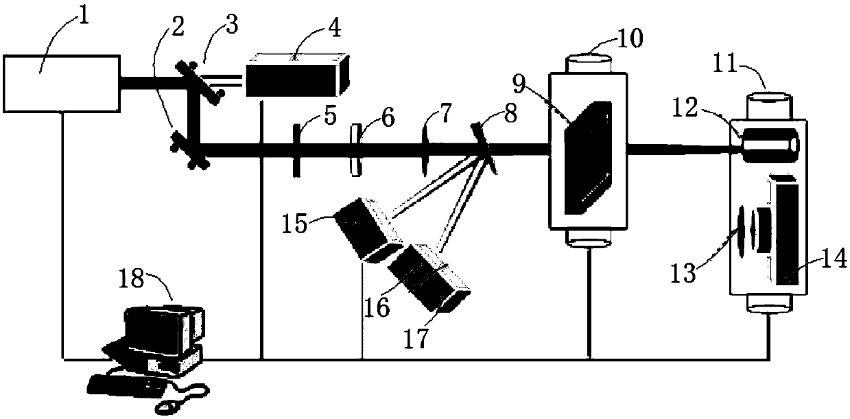
[0053] Such as figure 1 As shown, this embodiment provides a high-precision measuring device for DKDP crystal body damage performance, including a laser 1, a first mirror 3, a second mirror 2, an energy meter 4, a polarizer 5, a 1 / 2 wave plate 6, Focusing lens 7, optical wedge 8, CCD camera 15, photocell 16, oscilloscope 17, three-dimensional translation stage 10, ring light source 9, broadband polarizer 13, microscope 14, absorption trap 12 and PC computer 18, also includes two-dimensional translation stage 11 and two translation stage drive controllers (not shown) that are respectively connected with the two-dimensional translation stage 11 and the three-dimensional translation stage 10, the field of view of the microscope 14 can be spliced ​​and is larger than the spot size on the crystal sample to be measured, The lateral resolution of the microscope 14 is less than 1 μm, the working distance of the microscope 14 is greater than the thickness of the crystal sample to be me...

Embodiment 2

[0073] This embodiment is further optimized on the basis of Embodiment 1, specifically:

[0074] In S4, the two-dimensional translation stage 11 and the three-dimensional translation stage 10 are controlled by the PC computer 18, so that the microscope 14 performs three-dimensional tomographic photography of the area to be tested, specifically:

[0075] S4.1: Record the three-dimensional coordinates of the shooting starting point, and control the drive controller of the translation platform through the PC computer 18, thereby controlling the movement of the two-dimensional translation platform 11, so that the microscope 14 laterally photographs a certain tomographic surface of the area to be measured;

[0076] S4.2: After the horizontal shooting of the tomographic surface is completed, the three-dimensional translation stage 10 is controlled by the PC computer 18, so that the three-dimensional translation stage 10 is stepped along the longitudinal direction of the crystal sampl...

Embodiment 3

[0080] This embodiment is further optimized on the basis of Embodiment 1, specifically:

[0081] Described S6 specifically comprises the following steps:

[0082] S6.1: Use 3D image processing software, such as Avizo, Amira, etc., to subtract the picture before damage measurement from the picture after damage measurement to obtain the damage map after pulse action;

[0083] S6.2: Eliminate the impact of the surface factors of the crystal sample to be tested on the pulse effect, solve the problems of repeated statistics of damage points, background light elimination, binarization, etc., and use the image moment algorithm to find the centroid of each scattering point;

[0084]S6.3: Perform three-dimensional reconstruction on all tomographic images of the damage map after excluding the influence, and obtain the three-dimensional distribution of damage points in the crystal body;

[0085] S6.4: Analyze the image obtained after three-dimensional reconstruction to obtain the number...


PUM


Abstract

The invention discloses a (D)KDP crystal body damage performance high-precision measurement device and measurement method, relating to the technical field of (D)KDP crystal body damage measurement. According to the method, crystal body damage point base data after action of high power nanosecond laser pulse is acquired through chromatography, problems like damage point repeated statistics, background light elimination and binarization are solved, center of mass of each scattering point is resolved by using an image moment algorithm, then body damage point three-dimensional distribution is acquired through a reconstruction algorithm, then three body damage representation parameters, including crystal body damage density ppd, body damage point geometric size distribution pps and crystal bodydamage point three-dimensional distribution can be acquired highly precisely. The method has the advantages of high measurement accuracy and more complete crystal body damage representation.

Description

technical field [0001] The invention relates to the technical field of (D)KDP crystal body damage measurement, and more specifically relates to a high-precision measurement device and a measurement method for (D)KDP crystal body damage performance. Background technique [0002] (D) Due to the fast growth rate (10mm / day) and the ability to grow to a larger (~40cm) geometric size, KDP crystal is currently the only frequency conversion material available in laser inertial confinement fusion drivers. A large number of experiments have confirmed that in Under the action of nanosecond laser pulses far below the intrinsic damage threshold, (D)KDP crystals often exhibit bulk damage, which usually appears in large numbers (~10 3 / mm 3 ), geometric dimensions between 10 0 ~10 1 Needle-shaped damage points on the order of μm. The appearance of body damage points will not only increase the scattering loss, but also increase the contrast of the downstream beam, which will induce dama...

Claims


Application Information

Patent Timeline
Patent Type & Authority Applications(China)
IPC IPC(8): G01N21/958
CPCG01N21/958
Inventor 郑垠波巴荣声丁磊周信达李杰徐宏磊李亚军那进张霖刘勇石振东马骅刘昂徐凯源万道明白金玺
Owner LASER FUSION RES CENT CHINA ACAD OF ENG PHYSICS
Why Eureka
Try Eureka