Automatic wire feeding device for additive manufacturing and using method thereof

A wire feeding device and additive manufacturing technology, which is applied to auxiliary devices, manufacturing tools, auxiliary welding equipment, etc., can solve the problems of unfavorable continuous printing, high repurification cost, and atmosphere damage in the atmosphere chamber, so as to improve the wire feeding efficiency and The degree of automation, the avoidance of splashes and metal losses, the effect of reducing economic costs

Pending Publication Date: 2019-04-02
NAT INST CORP OF ADDITIVE MFG XIAN
View PDF0 Cites 4 Cited by
  • Summary
  • Abstract
  • Description
  • Claims
  • Application Information

AI Technical Summary

Problems solved by technology

[0004] In the existing additive manufacturing fuse system, the wire feeding system is mostly placed inside the atmosphere chamber or exposed outside; if the wire feeding system is placed outside the atmosphere chamber, the air will enter the molten pool along the wire feeding tube along with the welding wire, increasing During the material manufacturing process, the accumulation layer is seriously oxidized at high temperature; if it is placed inside the atmosphere chamber, the atmosphere protection can be effectively carried out, but the welding wire cannot be replaced continuously, and the atmosphere chamber hatch needs to be opened to enter the atmosphere chamber for replacement, which will cause atmosphere The room atmosphere is destroyed, and there are problems such as high cost and long purification time for re-purification, which is not conducive to continuous printing in additive manufacturing; and in the existing wire feeding system, most of the wire feeding brackets use curved pipes to feed wires, and only the height of the welding wire can be adjusted , the wire feeding elevation angle between the welding wire and the base plate cannot be adjusted, and the welding wire sent out is in the shape of a curved arc and cannot effectively enter the molten pool

Method used


Image

  • Automatic wire feeding device for additive manufacturing and using method thereof

Examples


Embodiment Construction

[0034] The present invention is described in further detail below in conjunction with accompanying drawing:

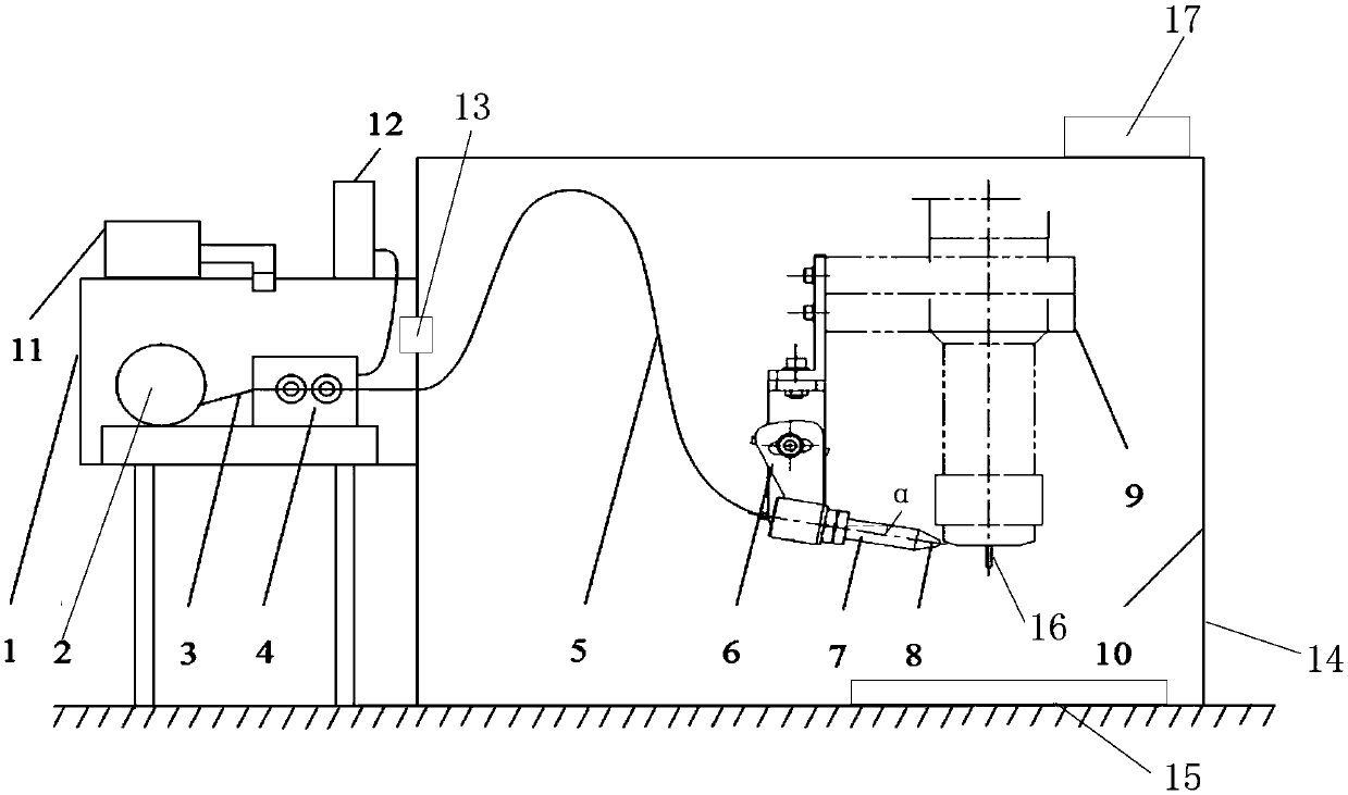
[0035] see figure 1 , the invention discloses an automatic wire feeding device for additive manufacturing and its use method; Support 6, wire feeding tube 7, wire feeding nozzle 8, heat source 9, atmosphere chamber 10, first atmosphere purification device 11, wire feeder controller 12, communication valve 13, atmosphere chamber sealing port 14, substrate 15, heat source output end 16 and the second atmosphere purification device 17.

[0036] The transition chamber 1 is fixed on the outside of the atmosphere chamber 10, the top of the transition chamber 1 is fixedly equipped with a first atmosphere purification device 11 and a wire feeder controller 12, and the side wall of the transition chamber 1 is provided with a door, which is convenient for the wire feeder 2 The replacement of the first atmosphere purification device 11 is provided with a gas pipeline connected ...


PUM


Abstract

The invention discloses an automatic wire feeding device for additive manufacturing and a using method thereof. The device arranges a wire feeding device and an additive manufacturing device in two independent cabins, the internal atmospheres of the two cabins are independent and sealed, the two cabins can be independently vacuumized or cleaned, so that when the wire feeding device is used for replacing the welding wires many times, the atmosphere of the additive manufacturing at the cabin body does not need to be damaged, and the quality of the product manufactured by the additive is influenced. According to the device, the problem of unsmooth wire feeding and the problem of the wire replacement of the welding wire under the condition that atmosphere protection are not damaged are effectively solved, the economic cost is reduced; the welding wire and the additive manufacturing method are high in flexibility and high in operability, the wire feeding efficiency and the automation degreein the by-shaft wire feeding process are effectively improved; meanwhile, the wire feeding terminal is used for feeding the wire through the wire feeding tube and the wire feeding nozzle and is a straight pipe wire feeding mode and has a straightening function on a welding wire.

Description

【Technical field】 [0001] The invention belongs to the fields of metal welding and additive manufacturing, and in particular relates to an automatic wire feeding device for additive manufacturing and a usage method thereof. 【Background technique】 [0002] With the development of additive manufacturing technology, fused wire additive manufacturing is one of the hot research fields; the principle of fused wire additive manufacturing is: use drawing software to design the three-dimensional model of parts, and then use "slicing" according to the structure of parts The software performs layering and slicing, and then generates the corresponding path planning program code, and then uses the method of fuse additive manufacturing to stack layer by layer according to the planned path, and finally forms a three-dimensional solid part blank. [0003] The heat sources for additive manufacturing of fuses mainly include arcs, electron beams, lasers, etc. Since the high temperature in the p...

Claims


Application Information

Patent Timeline
Patent Type & Authority Applications(China)
IPC IPC(8): B23K37/00
CPCB23K37/00
Inventor 方学伟张丽娟许康卓君禄娟张宇欣赵纪元卢秉恒
Owner NAT INST CORP OF ADDITIVE MFG XIAN
Why Eureka
Try Eureka