
Novel composite diaphragm wall structure under low clearance and construction method of novel composite diaphragm wall structure

A ground connection wall and low headroom technology, which is applied in foundation structure engineering, sheet pile walls, buildings, etc., can solve problems such as long hoisting and splicing time, affecting the overall mechanical performance of the ground connection wall, and insufficient assembly

Pending Publication Date: 2019-04-02
SHANGHAI NO 4 CONSTR
View PDF0 Cites 2 Cited by
  • Summary
  • Abstract
  • Description
  • Claims
  • Application Information

AI Technical Summary

Problems solved by technology

Therefore, there are often problems such as long hoisting and splicing time, insufficient assembly, and high assembly cost, which increases the difficulty of construction of the ground connection wall and affects the overall mechanical performance of the ground connection wall.

Method used


Image

  • Novel composite diaphragm wall structure under low clearance and construction method of novel composite diaphragm wall structure
  • Novel composite diaphragm wall structure under low clearance and construction method of novel composite diaphragm wall structure
  • Novel composite diaphragm wall structure under low clearance and construction method of novel composite diaphragm wall structure

Examples


Embodiment Construction

[0041] The present invention will be described in further detail below in conjunction with the accompanying drawings and specific embodiments. The technical content and features of the present invention will be described in detail below by referring to the illustrated embodiments in conjunction with the accompanying drawings. It should be further noted that all the drawings are in very simplified form and use imprecise scales, and are only used to facilitate and clearly assist the purpose of illustrating the embodiments of the present invention. For the convenience of description, the "up" and "down" described below are consistent with the directions of up and down in the drawings, but this should not be a limitation of the technical solution of the present invention.

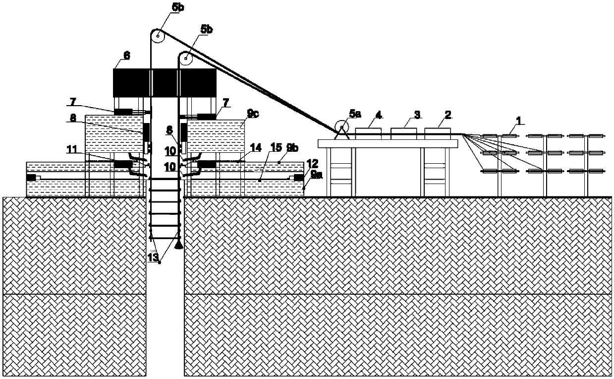
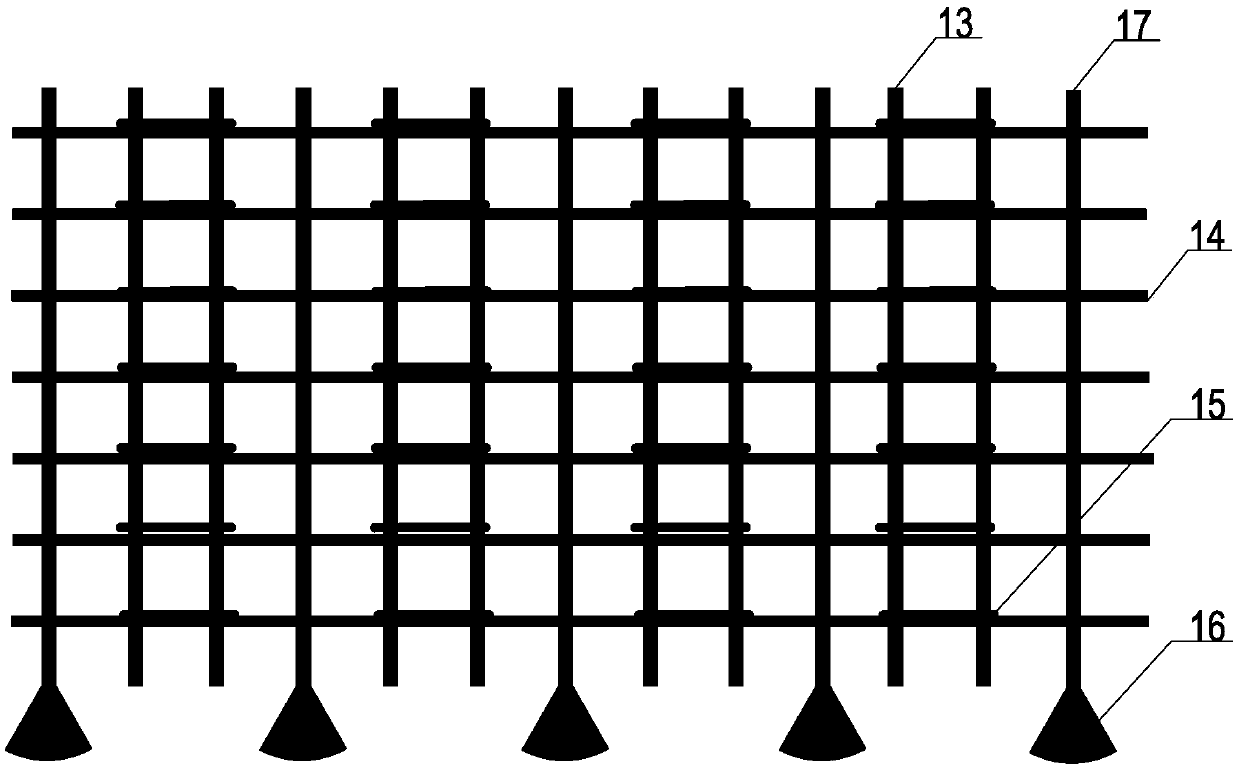
[0042] see Figure 1 to Figure 11 , this embodiment discloses a new composite ground wall structure under low headroom, including a ground wall frame formed by ground wall skeleton and concrete pouring, the gr...


PUM


Abstract

The invention discloses a novel composite diaphragm wall structure under the low clearance and a construction method of the novel composite diaphragm wall structure. A diaphragm wall frameworkis assembled and formed by directly connecting fiber reinforced polymer (FRP) bars and ordinary steel bars in a groove of a diaphragm wall, the fiber reinforced polymer (FRP) bars are arranged longitudinallyinto two rows to be used as vertical longitudinal bars along a wall body of the diaphragm wall, and the corresponding row, close to the excavation side of a foundation pit, of the vertical longitudinal bars are fiber reinforced polymer (FRP) prestressed bars; the diaphragm wall framework is directly arranged in the ground of the diaphragm wall after continuous pultrusion molding through the fiberreinforced polymer (FRP) bars, no lifting and splicing is required, and the diaphragm wall framework is not limited by the clearance. According to the novel composite diaphragm wall structure under the low clearance and the construction method of the novel composite diaphragm wall structure, a prestressed technology is applied, the flexural rigidity of the composite diaphragm wall is automaticallyadjusted and lifted while the tensile strength of the flexible fiber reinforced polymer (FRP) bars is fully utilized, and thus load-bearing performance of thediaphragm wall can meet the force suffering requirements under different working conditions; and in addition, the diaphragm wall framework formed by combining the flexible fiber reinforced polymer (FRP) bars and the ordinary steel bars can automatically adapt to the groove size of the diaphragm wall anddeal with the special adverse conditions such as irregular groove walls, the load-bearing capacity is higher, materials are more economical, and construction is more convenient.

Description

technical field [0001] The invention relates to the field of ground connection wall construction, in particular to a novel composite ground connection wall structure and a construction method under low headroom. Background technique [0002] Usually, when carrying out ultra-deep ground connection wall construction in a small space and low headroom, it is often difficult to hoist the ground connection wall reinforcement cage. Due to the limitations of the clear height and the site, the ground connection wall reinforcement cage often needs to be hoisted and assembled in sections connect. Therefore, there are often problems such as long hoisting and splicing time, insufficient assembly, and high assembly cost, which increases the construction difficulty of the ground connection wall and affects the overall mechanical performance of the ground connection wall. [0003] Therefore, how to provide a new type of composite floor-connected wall structure and construction method under...

Claims


Application Information

Patent Timeline
IPC IPC(8): E02D5/18
CPCE02D5/18
Inventor 孙沈鹏谷志旺王伟茂张波汪小林蔡观生陈雪峡何娇
Owner SHANGHAI NO 4 CONSTR
Learn More