Rail operation vehicle transmission system

A technology for working vehicles and transmission systems, applied in the field of railway engineering machinery, can solve the problems of complex power system structure and various equipment, and achieve the effects of reducing manufacturing costs, saving space and weight, and simple control

Active Publication Date: 2019-04-05
ZHUZHOU TIMES ELECTRONICS TECH CO LTD +1
View PDF12 Cites 3 Cited by
  • Summary
  • Abstract
  • Description
  • Claims
  • Application Information

AI Technical Summary

Problems solved by technology

Also for example: CN105256675A and No. CN104742918A Chinese invention applications have provided the electric transmission system and power switching method of the dual-power subway grinding car, but the structure of the power system of the double-power subway grinding car involved is complex and the equipment is various

Method used


Image

  • Rail operation vehicle transmission system
  • Rail operation vehicle transmission system
  • Rail operation vehicle transmission system

Examples


Embodiment 1

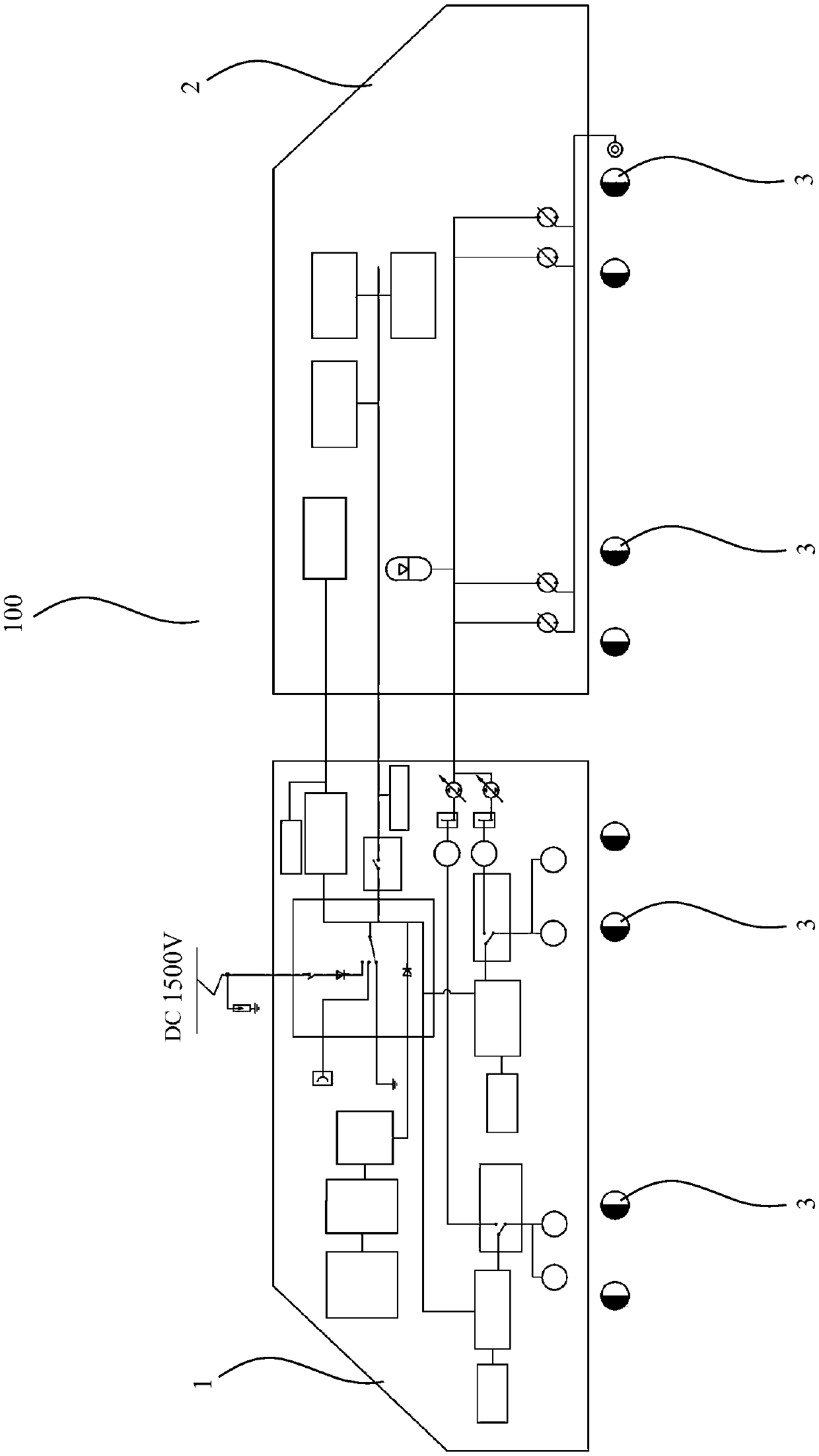
[0042] as attached figure 1 As shown, an embodiment of the transmission system of the rail working vehicle of the present invention, the rail working vehicle 100 includes a power vehicle 1 and a working vehicle 2, and the transmission system specifically includes: a vehicle power supply system arranged on the power vehicle 1, a high-speed running system and a low-speed travel power source, a low-constant-speed travel system arranged on the work vehicle 2, and a part or all of the work system arranged on the work vehicle 2. The vehicle power supply system provides power for the operating system, and can optionally provide power for the high-speed traveling system or low-speed traveling power source. The high-speed traveling system adopts the electric drive traction system to realize the traveling speed of the rail operating vehicle at 0-80km / h. And the speed control accuracy is less than 0.5km / h. The low-speed running power source provides the hydraulic power source for the lo...

Embodiment 2

[0066] Another embodiment of the rail working vehicle transmission system of the present invention, the rail working vehicle 100 includes a power vehicle 1 and a working vehicle 2, and the transmission system specifically includes: a vehicle power supply system and a high-speed running system arranged on the power vehicle 1, arranged The low constant speed travel system and the low speed travel power source on the work vehicle 2, and part or all of the work system arranged on the work vehicle 2. The vehicle power supply system provides power for the operating system, and can optionally provide power for the high-speed traveling system or low-speed traveling power source. The high-speed traveling system adopts the electric drive traction system to realize the traveling speed of the rail operating vehicle at 0-80km / h. And the speed control accuracy is less than 0.5km / h. The low-speed running power source provides the hydraulic power source for the low-constant-speed running syst...

Embodiment 3

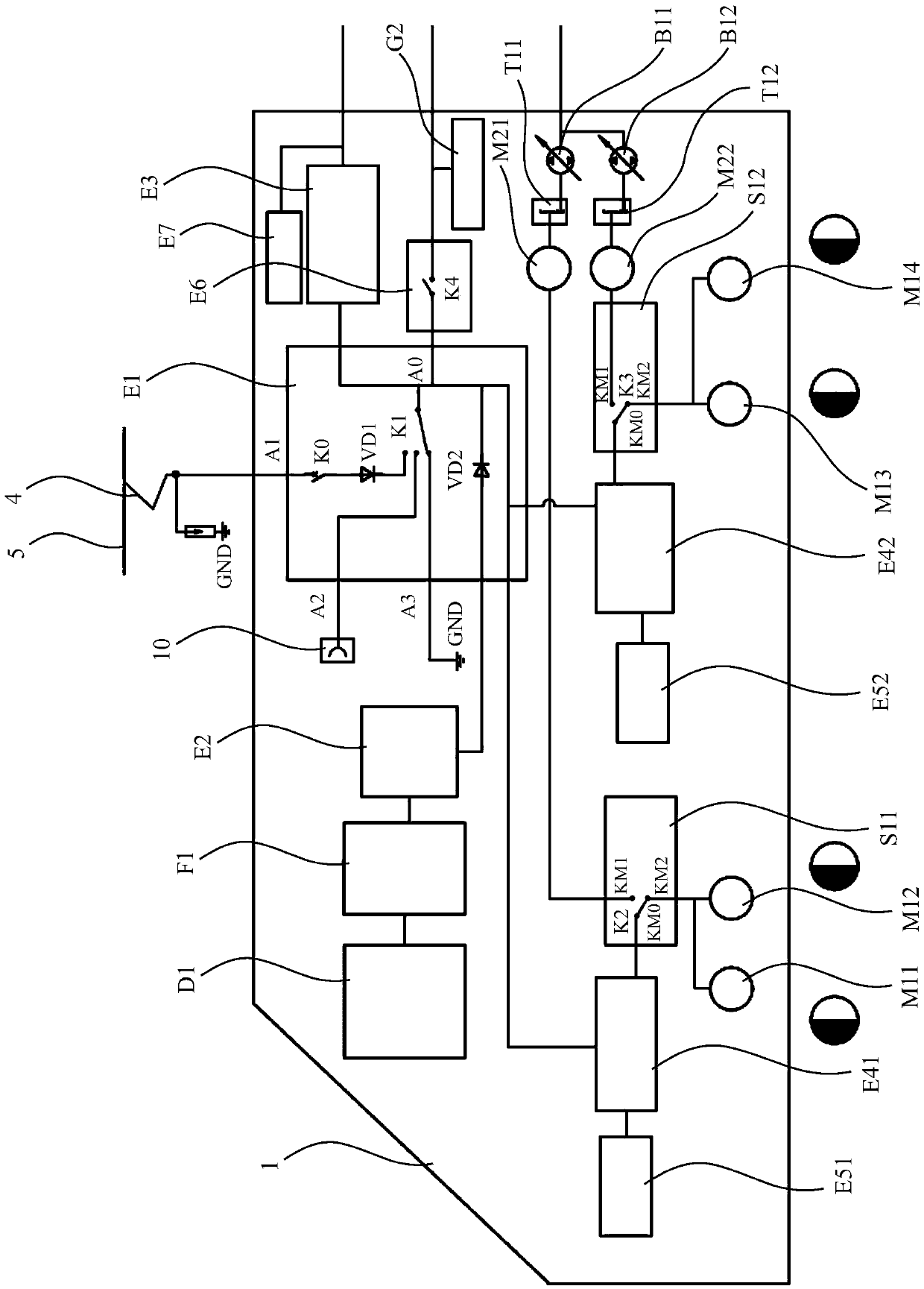
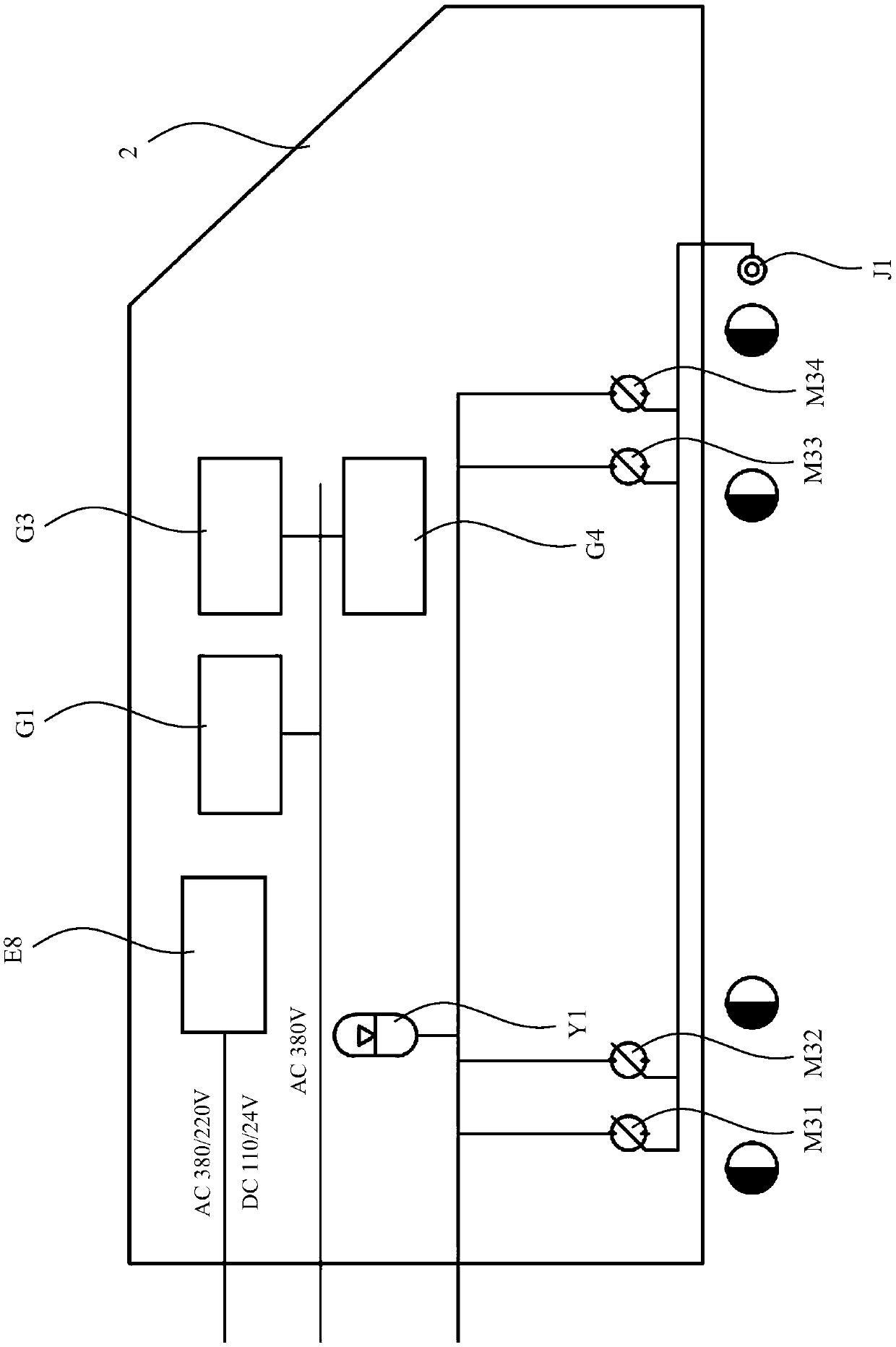
[0069] as attached Figure 4 And attached Figure 5 As shown, the rail work vehicle 100 involved in this embodiment is composed of a power vehicle 1 and an operation vehicle 2. The power vehicle 1 is responsible for providing the vehicle power supply, high-speed travel power and low-speed travel power source, and the operation vehicle 2 is responsible for providing operation functions and realizing Walk at a low constant speed. Wherein, the power car 1 includes an electrical room 11 , a power room 12 and an iron chip cabin 13 . The electrical room 11 is arranged with a high voltage box E1, a rectifier cabinet E2, an operation power supply box E6, a storage battery E7 and a control cabinet 101 (a control system is arranged inside). The power room 12 is arranged with an engine D1, a generator F1 and the like. The chip cabin 13 is arranged with a brake system cabinet 102 (with air braking equipment arranged therein), a milling chip cabin 1 103 and a milling chip cabin 2 104 . ...


PUM


Abstract

The invention discloses a rail operation vehicle transmission system. A rail operation vehicle comprises a power vehicle and an operation vehicle; the rail operation vehicle transmission system comprises a vehicle power supply system, a high speed running system and a low speed running power source, a low constant speed running system and an operation system, wherein the vehicle power supply system, the high speed running system and the low speed running power source are placed on the power vehicle; the low constant speed running system is placed on the operation vehicle; and the operation system is partially or totally placed on the operation vehicle. The vehicle power supply system provides a power supply for the operation system and can selectively provide power supply for the high speed running system or the low speed running power source; and the high speed running system adopts an electric drive traction system. The low speed running power source provides a hydraulic power sourcefor the low constant speed running system; and the low constant speed running system adopts an electric drive hydrostatic transmission traction system. According to the rail operation vehicle transmission system, a technical problem of power transmission of a double-power-source rail operation vehicle in high speed running and low running modes can be solved to satisfy requirements on a running speed and control accuracy under different working conditions.

Description

technical field [0001] The invention relates to the technical field of railway engineering machinery, in particular to a transmission system structure of a dual power source driven rail vehicle. Background technique [0002] As a widely used rail operating vehicle, the rail milling and grinding vehicle is a rail engineering maintenance vehicle used to repair rail surface defects. The rail milling and grinding vehicle processes the surface of the rail through the milling unit and the grinding unit installed on the vehicle chassis, so that the parameters such as the roughness, wave grinding and profile of the rail surface reach the required value. The cutter on the milling unit mills the surface of the rail to eliminate damage and corrugation on the surface of the rail to control the cross-sectional profile. The grinding wheel on the grinding unit grinds the rail surface after milling chips to make the rail surface smoother and reach the required roughness value. The rail mi...

Claims


Application Information

Patent Timeline
Patent Type & Authority Applications(China)
IPC IPC(8): E01B31/13E01B31/17
CPCE01B31/13E01B31/17
Inventor 雷张文李石平王建宏肖少坤肖樨李永江汪海曹增明贺旭贺占龙童开
Owner ZHUZHOU TIMES ELECTRONICS TECH CO LTD
Why Eureka
Try Eureka