Forced cooling system for wind turbine unit pitch control cabinet

A wind turbine and forced cooling technology, which is applied to wind engines, engines, wind power generation, etc., can solve the problems of low cooling efficiency and achieve the effects of improving cooling efficiency, improving heat dissipation efficiency, and low energy consumption costs

Inactive Publication Date: 2019-04-05
大唐向阳风电有限公司
View PDF16 Cites 1 Cited by
  • Summary
  • Abstract
  • Description
  • Claims
  • Application Information

AI Technical Summary

Problems solved by technology

[0003] The purpose of the present invention is: in order to solve the technical problem of low cooling efficiency of the pitch control cabinet of the existing wind turbine, the present invention provides a forced cooling system for the pitch control cabinet of the wind turbine

Method used


Image

  • Forced cooling system for wind turbine unit pitch control cabinet

Examples


Embodiment 1

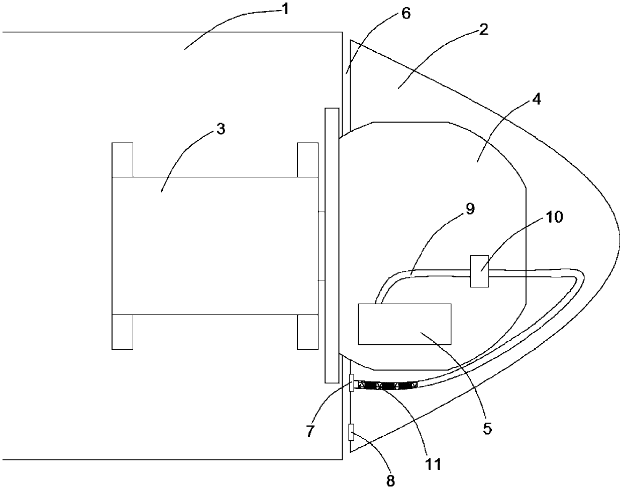
[0021] Such as figure 1 As shown, this embodiment provides a forced cooling system for a pitch control cabinet of a wind turbine, including a wind turbine and a pitch control device, and the wind turbine includes a nacelle 1 and a shroud 2 arranged on the top of the nacelle 1, and The control system includes a pitch control cabinet 5. A main shaft 3 is arranged inside the nacelle 1. The top of the main shaft 3 is connected with a hub 4 arranged inside the spinner 2. The pitch control cabinet 5 is arranged inside the hub 4. The spinner 2 and the nacelle There is a gap 6 of 3cm to 7cm between 1, the gap 6 directly communicates with the outside world, the side of the hub 4 in the gap 6 is provided with an air inlet 7 and a pressure-reducing port 8, and the air inlet 7 is connected to the air guide cover 2 The air inlet pipe 9 directly communicates with the pitch control cabinet 5, and the air inlet pipe 9 is provided with a blower fan 10.

[0022] Through the gap between the air...

Embodiment 2

[0024] Such as figure 1 As shown, this embodiment is further optimized on the basis of embodiment 1, specifically:

[0025] There is a gap 6 of 5 cm between the wind deflector 2 and the nacelle 1 .

[0026] The outer diameter of the nacelle 1 is 5 cm to 7 cm larger than the outer diameter of the bottom surface of the wind deflector 2 .

[0027] The outer diameter of the nacelle 1 is slightly larger than the outer diameter of the bottom surface of the shroud 2, so that the external air flow can be blocked by the shunt of the shroud 2, and more cold air can enter the gap 6, so that the fan 10 can more easily suck in the outside air, reducing Energy consumption, improve practicality.

Embodiment 3

[0029] Such as figure 1 As shown, this embodiment is further optimized on the basis of embodiment 2, specifically:

[0030] The bottom surface of the hub 4 is evenly opened with a plurality of air inlets 7 in the circumferential direction, and each air inlet 7 is connected to an air inlet pipe 9 respectively, and all the air inlet pipes 9 are connected to the pitch control cabinet 5, and each air inlet pipe 9 is provided with There are fan 10.

[0031] A plurality of air inlet pipes 9 are evenly distributed inside the air guide 2, which can effectively improve the cooling efficiency. At the same time, the heat exchange through the air inlet pipes 9 can reduce the temperature in the air guide 2, thereby improving the temperature of all electrical appliances in the air guide 2. Component cooling effect.


PUM


Abstract

The invention discloses a forced cooling system for a wind turbine unit pitch control cabinet, and relates to the technical field of heat dissipation of a wind turbine unit pitch control system. In order to solve the technical problem of low cooling efficiency of existing wind turbine unit pitch control cabinets, the forced cooling system comprises a wind turbine unit and a pitch control device, wherein the wind turbine unit comprises a cabin and a fairing arranged at the top of the cabin, and the pitch control system comprises a pitch control cabinet body. The forced cooling system is characterized in that a spindle is arranged in the cabin, the top of the spindle is connected with a hub arranged in the fairing, the pitch control cabinet body is arranged in the hub, a gap of 3-7 cm is reserved between the fairing and the cabin and directly communicates with the outside, an air inlet and a pressure reducing opening are formed in the side, where the hub is located, in the gap, the air inlet is connected with an air inlet pipe arranged in the fairing, and the air inlet pipe directly communicates with the pitch control cabinet body and provided with a fan. The forced cooling system has the advantages of being high in cooling efficiency, low in energy consumption and high in practicability.

Description

technical field [0001] The invention relates to the technical field of heat dissipation of a pitch control system of a wind turbine, and more particularly relates to a forced cooling system for a pitch control cabinet of a wind turbine. Background technique [0002] The pitch system of wind turbines is divided into two categories: hydraulic pitch and electric pitch. Among them, the hydraulic pitch system has shortcomings such as nonlinearity, easy leakage, and jamming. Leakage not only easily causes unit operation failure, but also brings inconvenience to daily maintenance; the electric pitch system uses a motor with a reducer to control the blades individually , which has a compact and reliable structure and can be independently adjusted. The electric pitch system is mainly composed of four parts: the pitch controller, the backup power supply, the servo driver and the motor. In the cabinet, due to the consideration of the working environment, most of the electrical compon...

Claims


Application Information

Patent Timeline
Patent Type & Authority Applications(China)
IPC IPC(8): F03D80/60F03D80/55
CPCF03D80/55F03D80/60Y02E10/72
Inventor 孟晓曦刘洋刘一诺薛莹
Owner 大唐向阳风电有限公司
Why Eureka
Try Eureka