Device and method for testing wave erosion resistance of soil body or soft rock

A wave and soil technology, which can be used in measuring devices, testing wear resistance, and weighing by removing certain components. The effect of poor erosion capability

Active Publication Date: 2019-04-05
CHINA THREE GORGES UNIV
View PDF7 Cites 6 Cited by
  • Summary
  • Abstract
  • Description
  • Claims
  • Application Information

AI Technical Summary

Problems solved by technology

[0003] The technical problem to be solved by the present invention is to provide a device and method for testing the wave erosion resistance of soil or soft rock, which can solve the problem that there is no experimental device for testing the wave erosion resistance of soil or soft rock. The

Method used


Image

  • Device and method for testing wave erosion resistance of soil body or soft rock
  • Device and method for testing wave erosion resistance of soil body or soft rock
  • Device and method for testing wave erosion resistance of soil body or soft rock

Examples


Embodiment 1

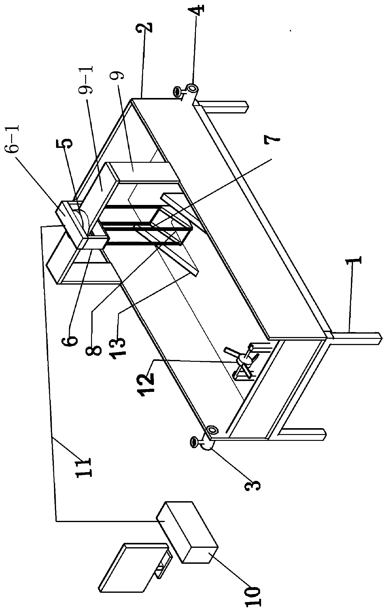
[0039] Such as Figure 1-Figure 2 As shown, a device for testing the ability of soil or soft rock to resist wave erosion includes a water tank body 2 arranged on a load-bearing frame 1. The water tank body 2 is respectively provided with a water inlet 3 and a water outlet 4. The grooves of the water tank body 2 There are scales on the wall;

[0040] A fixed frame 9 with a horizontal plate body 9-1 is installed on the tank body 2, a movable electronic balance 5 is placed on the horizontal plate body 14-1, and the force transmission frame 6 passes through the force transmission plate placed on the upper surface of the electronic balance 5 6-1 is installed on the fixed frame 9, the bottom of the force transmission frame 6 is hinged with the sample box 8 through a plurality of rods 7, and the sample box 8 is not in contact with the water tank body 2;

[0041] A wave maker 12 matched with the sample box 8 is installed in the tank body 2;

[0042] The electronic balance 5 is conne...

Embodiment 2

[0051] A method for testing soil or soft rock resistance to wave erosion by using the device described in any one of the above claims 1-5, the method may further comprise the steps:

[0052] Step 1: Close the water outlet 4 of the water tank body 2, open the water inlet 3 of the water tank body 2, and add water to the water tank body 2 until the initial calm water level is equal to or slightly higher than the height of the bottom surface of the sample box 8;

[0053] Step 2: Turn on the wave generator 12 and wait for a period of time until the generated waves are stable;

[0054] Step 3: Measure the water flow velocity at the part where the sample box 8 is to be installed in the tank body 2, and calculate the wave height according to the scale on the tank body 2;

[0055] Step 4: turn off the wave maker 12 and wait for a period of time until the water surface is calm and stable;

[0056] Step 5: Hang the sample box 8 containing the soil or soft rock sample on the electronic b...


PUM


Abstract

The invention discloses a device for testing wave erosion resistance of soil body or soft rock. The device comprises a water tank body arranged on a bearing frame, a water inlet and a water outlet areformed on the water tank body, and the scale is formed on a tank wall of the water tank body; a fixed frame with a horizontal plate body is arranged on the water tank body, a movable electronic balance is arranged on the horizontal plate body, a force transmission frame is arranged on the fixed plate through a force transmission plate placed on an upper surface of the electronic balance, the bottom of the force transmission frame is hinged with a sample box through multiple rods, and the sample box is out of touch the water tank body. Through the device and method for testing wave erosion resistance of soil body or soft rock disclosed by the invention, the problem that the device for testing the wave erosion resistance of the soil body or the soft rock is inexistent can be solved, a relation of the particle soil sample loss quality and loss rate and time is established by weighing the soil particle loss caused by wave washing, the wave erosion resistance of different soil body or softrock samples can be tested and determined according to evaluation standard.

Description

technical field [0001] The invention relates to the fields of water conservancy and rock soil experiments, in particular to a device and method for testing the ability of soil or soft rock to resist wave erosion. Background technique [0002] There are nearly 100,000 reservoirs and lakes of various types in my country, and nearly 50,000 rivers. The anti-wave erosion ability of slopes on both banks is mainly affected by internal and external factors. The internal factors are mainly the composition of the rock and soil mass and the physical and mechanical indicators such as the moisture content, dry density, and cohesion c of the soil mass. The external factors are mainly the wave speed, wave height and cycle of reservoir water waves. At present, some scholars have tried to carry out qualitative field experiments, which better reflect the actual environment, but the experimental variables are difficult to control, time-consuming and labor-intensive, and measurement accuracy i...

Claims


Application Information

Patent Timeline
IPC IPC(8): G01N3/56G01N5/04
CPCG01N3/567G01N5/04G01N2203/0005G01N2203/0048
Inventor 陈勇崔宪东隆海鹏苏剑张瀚
Owner CHINA THREE GORGES UNIV
Why Eureka
Try Eureka