Contactor control circuit

A technology for controlling circuits and contactors, applied to circuits, relays, electrical components, etc., can solve problems such as low power factor

Active Publication Date: 2019-04-05
SHENZHEN NANYUN MICROELECTRONICS CO LTD +1
View PDF7 Cites 2 Cited by
  • Summary
  • Abstract
  • Description
  • Claims
  • Application Information

AI Technical Summary

Problems solved by technology

For example, in the patent application number 200510029373.2, the electromagnetic coil is powered in the form of a pulse, so that the electromagnetic coil works with a constant small current; using this method will not only generate a large number of harmonics, but also the effective value of the input current does not follow the input voltage , leading to a very low power factor, according to the technology to make a prototype, the actual PF value is less than 0.3

Method used


Image

  • Contactor control circuit
  • Contactor control circuit
  • Contactor control circuit

Examples


no. 1 example

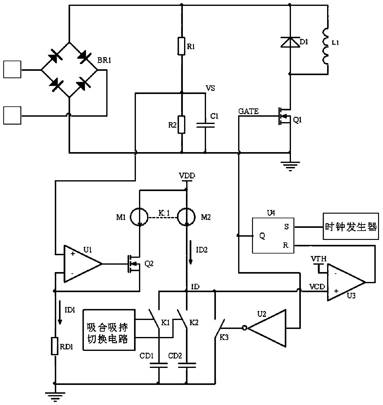
[0055] Such as figure 2 Shown is a schematic diagram of a contactor control circuit according to the first embodiment of the present invention, including a voltage detection circuit and a duty ratio control circuit.

[0056] The voltage detection circuit includes a resistor R1, a resistor R2 and a capacitor C1. The resistor R1 and the resistor R2 are connected in series and connected in parallel at both ends of the rectified bus voltage. One end of the capacitor C1 is connected to the connection point of the resistor R1 and the resistor R2, and serves as the output end of the voltage detection circuit, and the other end of the capacitor C1 is grounded. The function of the voltage detection circuit is to divide the voltage and filter, reduce the bus voltage to an appropriate value and extract its DC component.

[0057] The duty ratio control circuit of the first embodiment includes an operational amplifier U1, a MOS transistor Q2, a resistor RD1, a switch K1, a switch K2, a ...

no. 2 example

[0071] The circuit schematic diagram of the second embodiment is as follows Figure 4 shown. The basic principle of the second embodiment is the same as that of the first embodiment. The difference is that in the second embodiment, the charging current ID2 is controlled through the resistors RD1 and RD2 to set the duty cycle of the pull-in phase and the hold phase. The voltage detection circuit of the second embodiment is the same as that of the first embodiment. The connection relationship of the duty ratio control circuit of the second embodiment is as follows.

[0072]The duty ratio control circuit of the second embodiment includes an operational amplifier U1, a MOS transistor Q2, a resistor RD1, a resistor RD2, a switch K1, a switch K2, a switch K3, a capacitor CD1, an inverter U2, a comparator U3, and an RS flip-flop U4 , clock generator, suction and holding switching circuit, constant current source M1, constant current source M2. The positive input terminal of the o...


PUM


Abstract

The invention discloses a contactor control circuit. The contactor control circuit comprises a voltage detection circuit and a duty ratio control circuit. The voltage detection circuit is configured to reduce a bus voltage to a proper range through a divider resistor and filters an AC component through a low-pass filter, the rest of DC components are taken as output of the voltage detection circuit, and the output voltage is recorded as VS; the duty ratio control circuit detects the output voltage VS and outputs a duty ratio D, the VS*D is recorded as KD, wherein the KD is a constant set in the duty cycle control circuit. The KD is set as a constant to allow the a contactor coil current to be unchanged in a wide input range so as to omit the bus capacitance and the sampling resistance while improving the PF value of a contactor power saver and allow the contact coil current average value to be constant and unchanged in the wide-voltage AC and DC input voltage range.

Description

technical field [0001] The invention relates to the field of AC contactors, in particular to a contactor power saver with power factor correction function. Background technique [0002] The traditional contactor operating system consists of a coil, a static iron core, an armature and a reaction spring. When the contactor coil is energized, a suction force is generated between the static iron core and the armature. When the suction force is greater than the spring reaction force, the armature is attracted to the static iron core until it contacts the static iron core. At this time, the main contact is closed. This process is called suction. combined process. The process in which the coil is continuously energized, the armature is in contact with the static iron core, and the main contacts are in a closed state is called the holding process. When the current in the coil is reduced or interrupted, the suction force of the static iron core to the armature decreases. When the s...

Claims


Application Information

Patent Timeline
Patent Type & Authority Applications(China)
IPC IPC(8): H01H47/32H01H47/02
CPCH01H47/02H01H47/325
Inventor 苏俊熙符威
Owner SHENZHEN NANYUN MICROELECTRONICS CO LTD
Why Eureka
Try Eureka