Shielding gas charging battery pack suitable for new energy automobile
A technology for new energy vehicles and battery packs, applied in electric vehicle charging technology, electric vehicles, secondary batteries, etc., can solve the problem of increasing the energy density of the battery system, increasing the structural weight of the battery pack, and the lack of a good solution for the battery pack To achieve the effect of enhancing the heat dissipation effect, improving the specific energy and safety, and reducing the harm of thermal runaway
- Summary
- Abstract
- Description
- Claims
- Application Information
AI Technical Summary
Problems solved by technology
Method used
Image

Examples
Embodiment 1
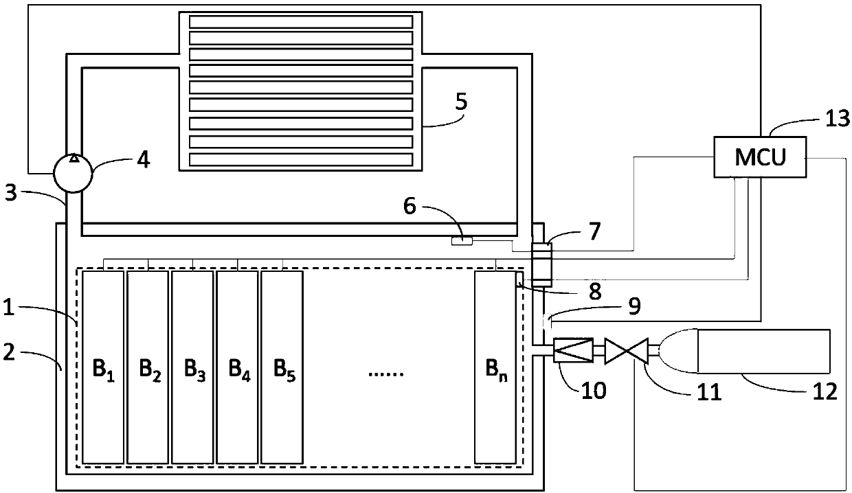
[0025] Such as figure 1 As shown, a gas-filled battery pack suitable for new energy vehicles, including:
[0026] A battery pack 1, which is formed by connecting multiple batteries in series / parallel;
[0027] The battery pack case 2 is a pressure-resistant sealed case filled with protective gas inside;
[0028] The air duct 3 is connected to the battery pack shell, the air pump and the radiator;
[0029] The air pump 4 is controlled by the MCU13, and its function is to make the protective gas flow along the conduit to the radiator;
[0030] The radiator 5 is located between the air pump 4 and the battery pack casing 2, which serves as a heat exchange between the internal protective gas and the external air;
[0031] The first air pressure sensor 6 is located in the inner cavity of the battery pack housing 2, and is used to feed back the inner cavity air pressure of the battery pack to the MCU13;
[0032] The electrical interface 7, where the voltage / current sampling signa...
Embodiment 2
[0043] Such as figure 1 As shown, a gas-filled battery pack suitable for new energy vehicles, including:
[0044] A battery pack 1, which is formed by connecting multiple batteries in series / parallel;
[0045] The battery pack case 2 is a pressure-resistant sealed case filled with protective gas inside;
[0046] The air duct 3 is connected to the battery pack shell, the air pump and the radiator;
[0047] The air pump 4 is controlled by the MCU13, and its function is to make the protective gas flow along the conduit to the radiator;
[0048] The radiator 5 is located between the air pump 4 and the battery pack casing 2, which serves as a heat exchange between the internal protective gas and the external air;
[0049] The first air pressure sensor 6 is located in the inner cavity of the battery pack housing 2, and is used to feed back the inner cavity air pressure of the battery pack to the MCU13;
[0050] The electrical interface 7, the internal pressure sensor 6, the temp...
Embodiment 3
[0061] Such as figure 1 As shown, a gas-filled battery pack suitable for new energy vehicles, including:
[0062] A battery pack 1, which is formed by connecting multiple batteries in series / parallel;
[0063] The battery pack case 2 is a pressure-resistant sealed case filled with protective gas inside;
[0064] The air duct 3 is connected to the battery pack shell, the air pump and the radiator;
[0065] The air pump 4 is controlled by the MCU13, and its function is to make the protective gas flow along the conduit to the radiator;
[0066] The radiator 5 is located between the air pump 4 and the battery pack casing 2, which serves as a heat exchange between the internal protective gas and the external air;
[0067] The first air pressure sensor 6 is located in the inner cavity of the battery pack housing 2, and is used to feed back the inner cavity air pressure of the battery pack to the MCU13;
[0068] The electrical interface 7, the internal pressure sensor 6, the temp...
PUM
 Abstract
Description
Claims
Application Information
 - R&D
- Intellectual Property
- Life Sciences
- Materials
- Tech Scout
- Unparalleled Data Quality
- Higher Quality Content
- 60% Fewer Hallucinations
Browse by: Latest US Patents, China's latest patents, Technical Efficacy Thesaurus, Application Domain, Technology Topic, Popular Technical Reports.
© 2025 PatSnap. All rights reserved.Legal|Privacy policy|Modern Slavery Act Transparency Statement|Sitemap|About US| Contact US: help@patsnap.com