A series-fed planar printed array antenna

An array antenna, plane technology, applied in the direction of antenna, resonant antenna, antenna array, etc., can solve the problems of interruption, communication system connection impact, etc.

Active Publication Date: 2019-04-05
NINGBO UNIV
View PDF7 Cites 4 Cited by
  • Summary
  • Abstract
  • Description
  • Claims
  • Application Information

AI Technical Summary

Problems solved by technology

In other words, if the horizontal polarization mode is used and the direction of the transmitter and receiver is tu

Method used


Image

  • A series-fed planar printed array antenna
  • A series-fed planar printed array antenna
  • A series-fed planar printed array antenna

Examples


Embodiment 1

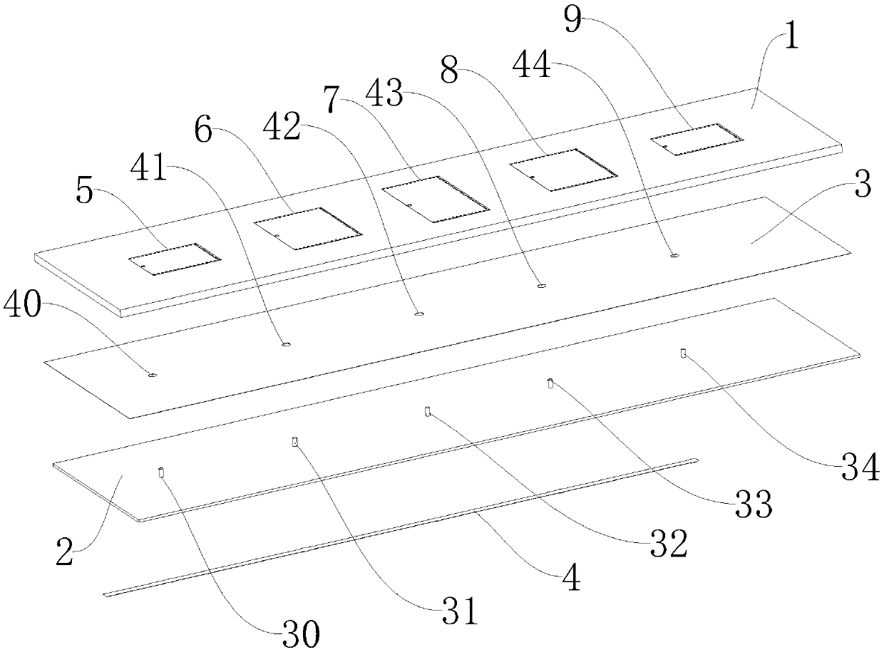
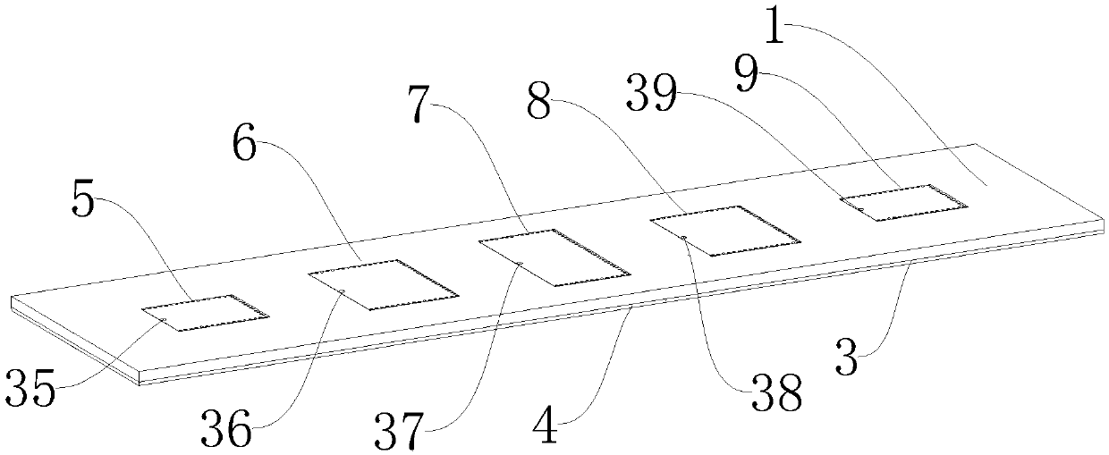
[0019] Embodiment 1: As shown in the figure, a series-fed planar printed array antenna includes an upper dielectric board 1, a lower dielectric board 2, a microstrip radiation group, a metal ground layer 3 and a microstrip feeder 4, the upper dielectric board 1, The lower dielectric board 2 and the metal grounding layer 3 are rectangular and the lengths of the long sides and wide sides of the three are respectively equal. The upper dielectric board 1, the metal grounding layer 3 and the lower dielectric board 2 are stacked together from top to bottom, and the metal grounding Layer 3 is attached to the upper surface of the lower dielectric board 2, the microstrip radiation group is arranged on the upper dielectric board 1, the microstrip feeder 4 is attached to the lower surface of the lower dielectric board 2, and the long side extension direction of the upper dielectric board 1 is taken as The left and right directions, the broadside extension direction as the front and rear d...

Embodiment 2

[0021] Embodiment two: this embodiment is basically the same as embodiment one, the difference is as follows:

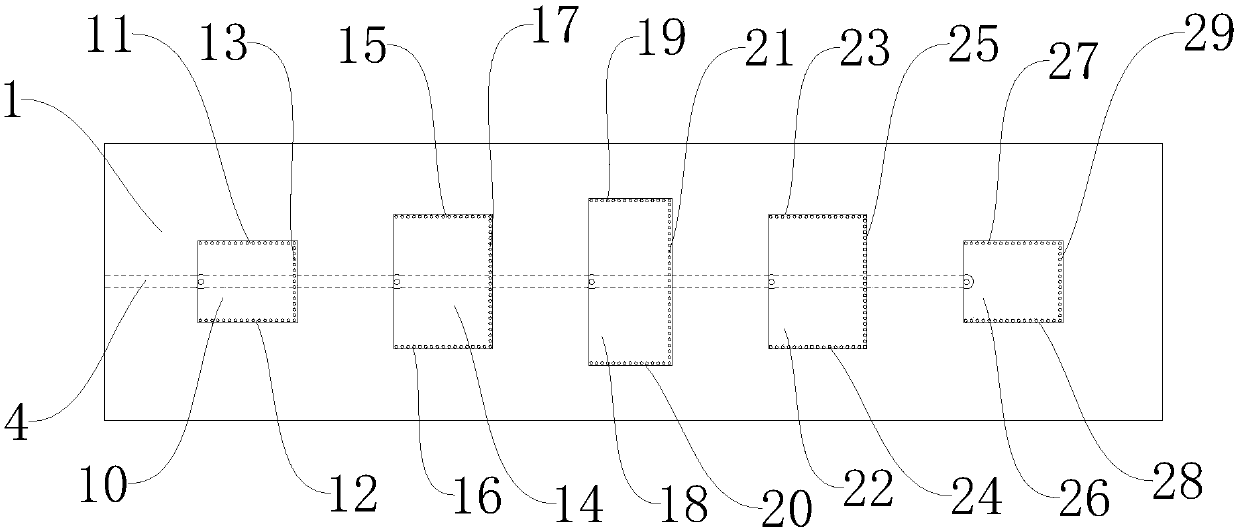
[0022]In this embodiment, the length of the long side of the first rectangular metal block 10 is 13.89 mm, and the length of the wide side is 11.44 mm. The first group of metallized through holes 11 is formed by 16 metallized through holes arranged at intervals from left to right. The second group of metallized through holes 12 is formed by 16 metallized through holes arranged at intervals from left to right, and the third group of metallized through holes 13 is formed by 15 metallized through holes arranged at intervals from front to back. The center distance between every two adjacent metallized through holes in the metallized through holes 11 and the center distance between every two adjacent metallized through holes in the second group of metallized through holes 12 are both 0.82 mm. The center distance between every two adjacent metallized through holes in the t...


PUM

PropertyMeasurementUnit
Long side lengthaaaaaaaaaa

Abstract

The invention discloses a series-fed planar printing array antenna comprising an upper dielectric plate, an underlying dielectric plate, a microstrip radiation group, a metal ground layer and a microstrip feeder line. The microstrip radiation group comprises a first microstrip radiation unit, a second microstrip radiation unit, a third microstrip radiation unit, a fourth microstrip radiation unitand a fifth microstrip radiation unit. The working modes of the first microstrip radiation unit, the second microstrip radiation unit, the third microstrip radiation unit and the fourth micro microstrip radiation unit and the fifth microstrip radiating unit are in a magnetic dipole working mode, and are arranged in order from left to right according to the Taylor line rule. The microstrip feeder line is separately connected with the first microstrip radiating unit, the two microstrip radiation unit, the third microstrip radiation unit, the fourth microstrip radiation unit and the fifth microstrip radiation unit. The advantages are that based on a simple structure and a low profile, electromagnetic waves with low side lobes and capable of vertical polarization of transmit-receive are provided.

Description

technical field [0001] The invention relates to a planar printed array antenna, in particular to a series-fed planar printed array antenna. Background technique [0002] The planar printed array antenna has the advantages of small size, light weight, low profile and simple processing and fabrication, and has broad application prospects. The existing planar printed array antenna mainly has two feeding methods: series feeding and parallel feeding. According to the feeding method, planar printed array antennas are divided into two categories: series-fed planar printed array antennas and parallel-fed planar printed array antennas. Compared with the parallel feeding method, the series feeding method has a shorter feeder line, which can effectively reduce the radiation and line loss caused by the feeder line, and improve the antenna efficiency. Therefore, the series-fed planar printed array antenna is relatively , in which the radiating units are arranged compactly, which can re...

Claims


Application Information

Patent Timeline
IPC IPC(8): H01Q1/38H01Q1/48H01Q1/50H01Q9/16H01Q21/00H01Q21/08
CPCH01Q1/38H01Q1/48H01Q1/50H01Q9/16H01Q21/0075H01Q21/08
Inventor 华昌洲赵启东刘梦靳翔宇陈国军
Owner NINGBO UNIV
Why Eureka
Try Eureka