Power-on reset circuit

An electrical reset and circuit technology, applied in data reset devices, electrical components, electronic switches, etc., can solve problems such as the inability to discharge the capacitor charge immediately, the increase of the layout area, and the inability of the circuit to generate a reset pulse signal, etc., to avoid continuous Reset pulse, the effect of increasing the layout area

Pending Publication Date: 2019-04-05
NO 47 INST OF CHINA ELECTRONICS TECH GRP
View PDF5 Cites 2 Cited by
  • Summary
  • Abstract
  • Description
  • Claims
  • Application Information

AI Technical Summary

Problems solved by technology

[0004] Aiming at the above-mentioned deficiencies in the prior art, the present invention provides a new power-on reset circuit, which completely solves the traditional RC power-on reset circuit. If you want a wider reset pulse, you must increase the capacitance of the capacitor. The area will increase. When the power supply voltage drops to zero rapidly, the capacitor charge cannot be discharged immediately, and the circuit cannot generate reset pulse signals when the power supply is powered on at this time.

Method used


Image

  • Power-on reset circuit
  • Power-on reset circuit
  • Power-on reset circuit

Examples


Embodiment Construction

[0020] The present invention will be further described in detail below in conjunction with the accompanying drawings and embodiments.

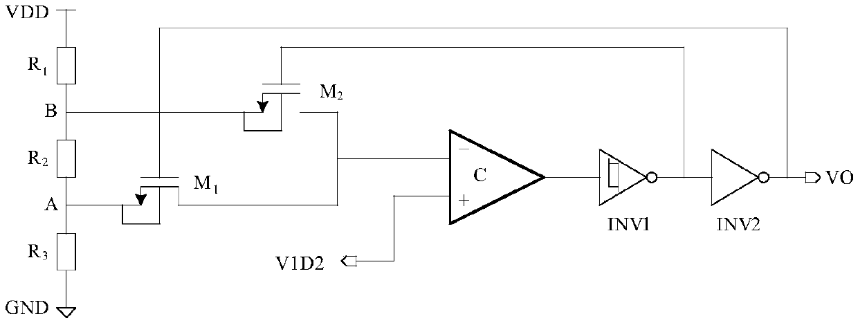
[0021] Such as figure 1 Shown is the power-on reset circuit of the present invention. The power supply VDD passes through the resistor R1, resistor R2, and resistor R3 in sequence, and then is grounded. The node B between the resistor R1 and the resistor R2 is connected to the source of the MOS transistor M2, and the node A between the resistor R2 and the resistor R3 is connected to the source of the MOS switch M1. The drain of MOS switch tube M1 and the drain of MOS switch tube M2 are respectively connected to the inverting input terminal of comparator C, the non-inverting input terminal of comparator C is connected to the reference voltage V1D2, and the output terminal of comparator C is sequentially passed through Schmidt The trigger INV1 and the inverter INV2 output the signal VO, the gate of the MOS switch M2 is also connected to the out...


PUM


Abstract

The invention relates to a power-on reset circuit with high reliability and low power consumption. The circuit uses the mode of combining a comparator and a Schmitt trigger. Compared with a previous RC power-on reset circuit, the circuit of the invention has a smaller area, lower power consumption and higher repeated power-on reliability, and has the performance characteristics that power-on and power-off thresholds can be set and so on. The reset circuit of the invention can be used to completely solve the disadvantage of the traditional RC power-on reset circuit, and the disadvantage is thatif a reset pulse is wide, the capacitance value of a capacitor has to be increased and a domain area is increased too. A problem that capacitor charges can not be discharged immediately when a powersupply voltage drops rapidly to zero is solved, and continuous reset pulses generated when a power supply is not stable can be avoided. The circuit does not use the capacitor. When power down and power on are performed rapidly, reset can be effectively performed. Hspice software is used to simulate the circuit, when the power supply voltage is 3.3V, a power-on threshold is set to be 3V, a power-down threshold is set to be 2.8V, and slow power-on and rapid power-down conditions have a good reset effect.

Description

technical field [0001] The invention relates to the field of integrated circuits, in particular to a power-on reset circuit. Background technique [0002] In the field of integrated circuits, both digital integrated circuits and hybrid integrated circuits use reset circuits, such as flip-flops, registers and other circuits. During the power-on process of the circuit, due to the extremely unstable power supply of the digital circuit, during this period The logic of the digital circuit is disordered, and it is easy to produce wrong logic. Therefore, the initial stage after the digital circuit is powered on needs a definite state, that is, the reset state, which requires a power-on reset circuit with very good performance. The power-on reset circuit needs to generate a reset pulse after the power supply is stable, so that the internal digital circuit of the system can be fully and reliably reset by this reset pulse. A power-on reset circuit with good performance should also ha...

Claims


Application Information

Patent Timeline
Patent Type & Authority Applications(China)
IPC IPC(8): H03K17/22G06F1/24
CPCH03K17/223G06F1/24
Inventor 范超王沦唐冬林雨佳荆洲张丹张禹
Owner NO 47 INST OF CHINA ELECTRONICS TECH GRP
Why Eureka
Try Eureka