Cooling waterway cycle structure of automobile engine

A technology of automobile engine and cooling water circuit, which is applied in the direction of engine cooling, engine components, combustion engine, etc., can solve the problems of reducing energy consumption, lack of comprehensive analysis and optimization of cylinder block water jacket and cylinder head water jacket, and difficulty in achieving results. , to reduce costs

Inactive Publication Date: 2019-04-09
SHENYANG AEROSPACE MITSUBISHI AUTOMOBILE ENGINE MFG CO LTD
View PDF0 Cites 0 Cited by
  • Summary
  • Abstract
  • Description
  • Claims
  • Application Information

AI Technical Summary

Problems solved by technology

[0003] In the past technology, electronic control was mainly aimed at a certain component in the cooling system, such as cooling water pump, electronic thermostat, etc., which only reduced the energy consumption of a single component, controlled a single circuit, and did not integrate all cooling water circuits of the engine. The flow and opening time are controlled, so there is no obvious effect on reducing...

Method used


Image

  • Cooling waterway cycle structure of automobile engine
  • Cooling waterway cycle structure of automobile engine
  • Cooling waterway cycle structure of automobile engine

Examples


Embodiment Construction

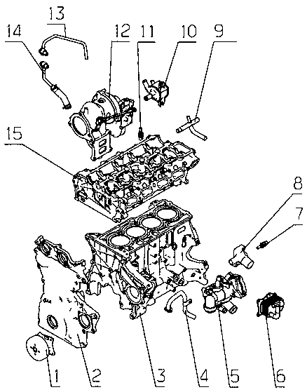
[0032] Referring to the accompanying drawings, an automobile engine cooling water circuit circulation structure includes an engine main water pump 1, a timing sprocket housing integrated water jacket 2, a cylinder block 3, a cylinder block water outlet pipe 4, a multi-channel coolant control valve 5, and an oil cooler 6. Water temperature sensor 7, cylinder block water outlet 8, cylinder head outlet pipe 9, electronic water pump 10, water temperature sensor 11, supercharger 12, supercharger return pipe 13, supercharger water inlet pipe 14, cylinder head 15, heat dissipation 16, expansion water tank 17, warm air heat exchanger 18, timing sprocket housing integrated water jacket 2 and engine main water pump 1 are arranged on the front face of cylinder block 3, and fixed by bolts, timing sprocket housing integrated water jacket 2 and the water inlet of the cylinder block 3 form the inner cavity of the engine main water pump 1, and the timing sprocket shell water jacket boss 19 is ...


PUM


Abstract

The invention discloses a cooling waterway cycle structure of an automobile engine, and is applied to the technical field of automobile engines. A timing sprocket housing integrated water jacket and an engine main water pump are arranged on the front end face of a cylinder block; the timing sprocket housing integrated water jacket and the water inlet position of the cylinder block form an inner cavity of the engine main water pump; a timing sprocket housing integrated water jacket boss is embedded into a water outlet passage of the engine main water pump of the cylinder block; a water jacket Aof the cylinder block and a water jacket B of a cylinder head communicate; and a first one lock pin is arranged at the air inlet side of the water jacket A of the cylinder block, and thus, most of cooling liquid enters the exhaust side of the water jacket A of the cylinder block from the air inlet side of the water jacket A of the cylinder block, and enters the engine main water pump to form a major cycle of the engine. According to the cooling waterway cycle structure disclosed by the invention, uniform flow area is guaranteed; the water pump is enough in head, and the resistance of waterways is overcome to make the cooling liquid reach corresponding positions; and according to different working conditions under which the engine is, the warm-up time is shorted, the combustion performanceis improved, the friction work is reduced, and the cooling loss is reduced.

Description

technical field [0001] The invention relates to an automobile engine cooling water circulation structure in the technical field of automobile engines. Background technique [0002] In recent years, the role of the engine cooling system is to keep the engine working in the most suitable temperature range under all working conditions. Today, with the increasingly stringent energy saving and emission reduction, various automobile manufacturers have begun to adopt the latest technological means and advanced manufacturing Process to reduce engine fuel consumption and emission of pollutants. How to accurately control the engine temperature to shorten the warm-up time, improve combustion performance, reduce friction work, and reduce cooling loss? Various manufacturers continue to study the engine cooling system and develop mechatronic products to realize the intelligence of the engine waterway chemical control. [0003] In the past technology, electronic control is mainly aimed a...

Claims


Application Information

Patent Timeline
IPC IPC(8): F01P3/20F01P5/10F01P7/14F01P7/16F01M5/02F01M5/00F02B29/04F02F1/16F02F1/36B60H1/04
CPCB60H1/04F01M5/002F01M5/005F01M5/021F01P3/20F01P5/10F01P7/14F01P7/165F01P2007/146F02B29/0443F02B29/0493F02F1/16F02F1/36Y02T10/12
Inventor 陆超张卫东张晓东朱强李想方博
Owner SHENYANG AEROSPACE MITSUBISHI AUTOMOBILE ENGINE MFG CO LTD
Why Eureka
Try Eureka