
Efficient swimming pool heat pump dehumidifier and working method thereof

A dehumidifier and heat pump technology, applied in the field of high-efficiency swimming pool heat pump dehumidifiers, can solve the problems of increasing unit size, increasing manufacturing costs, controlling costs, energy waste, etc., and achieve the effect of improving the energy efficiency of the whole machine

Active Publication Date: 2019-04-09
江苏致远高科能源科技有限公司
View PDF9 Cites 5 Cited by
  • Summary
  • Abstract
  • Description
  • Claims
  • Application Information

AI Technical Summary

Problems solved by technology

The resulting problem is: when the refrigeration system is working and the reheating condenser is working, if the surface cooler is fed with cold water, it will cause the process of cooling, dehumidification, reheating, and then cooling, which is a waste of energy.
For example, when used as a cold water surface cooler, it can only be started when the compressor is not working. With this configuration, the refrigeration system needs to be configured according to the full load, and the surface cooler also needs to be configured according to the full load, resulting in high initial cost of the unit.
In order to achieve both heating and cooling functions, some need to be equipped with two heat exchangers to undertake the functions of heating and cooling respectively, which greatly increases the manufacturing cost and control cost, and also increases the size of the unit

Method used


Image

  • Efficient swimming pool heat pump dehumidifier and working method thereof

Examples


Embodiment Construction

[0045] The present invention will be further illustrated below in conjunction with the accompanying drawings and specific embodiments. This embodiment is implemented on the premise of the technical solution of the present invention. It should be understood that these embodiments are only used to illustrate the present invention and are not intended to limit the scope of the present invention.

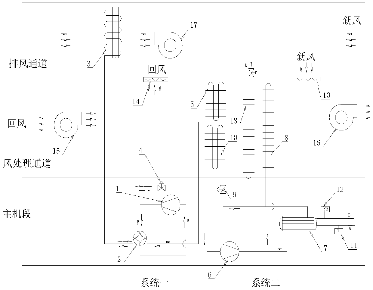
[0046] Such as figure 1 As shown, the embodiment of the present invention provides a high-efficiency swimming pool heat pump dehumidifier. The swimming pool heat pump dehumidifier includes more than two direct expansion systems. This embodiment uses two direct expansion systems as an example for illustration. The direction of the solid arrow in the figure indicates the flow direction of the refrigerant during the refrigeration cycle, and the direction of the dotted arrow indicates the flow direction of the refrigerant during the heat pump heating cycle.

[0047] Among the two direct exp...


PUM


Abstract

The invention discloses an efficient swimming pool heat pump dehumidifier and a working method thereof. The efficient swimming pool heat pump dehumidifier comprises a multipurpose heat exchanger and two or more than two refrigerating circulation systems, the multipurpose heat exchanger is installed between evaporators and reheating condensers of the two refrigerating circulation systems, differentmedia are introduced into the multipurpose heat exchanger in different seasons, and then different functions are achieved. According to the efficient swimming pool heat pump dehumidifier and the working method thereof, the multipurpose heat exchanger can meet different using requirements as needed, air can be treated step by step, various energy sources with different kinds of quality are fully utilized, and the purpose of improving the comprehensive energy efficiency is achieved; meanwhile, unit condensation heat is recycled and reutilized, the air feeding state is adjusted and improved, andthe pool hall temperature and humidity and the pool water temperature are adjusted; and in addition, air exhaust cold is recycled and used for lowering the unit condensation temperature, and the energy efficiency is improved. The unit integrated structure is adopted, an outdoor unit is omitted, energy loss brought to the refrigerating systems by long distance and large altitude difference is avoided, and the whole energy efficiency is improved from the multiple aspects.

Description

technical field [0001] The invention relates to the field of dehumidifiers, in particular to a high-efficiency swimming pool heat pump dehumidifier and its working method. Background technique [0002] With the continuous improvement of people's living standards, people not only require places where they can swim, but also put forward higher requirements for the swimming environment, and also need to ensure a certain amount of fresh air exchange. Therefore, the temperature and humidity control of indoor swimming pools is increasingly subject Widespread attention. When the relative humidity is too high, the indoor air quality cannot be guaranteed; when the relative humidity is too low, the pool water evaporates too fast, which will undoubtedly increase the input cost. In short, the air quality requirements in the pool hall are getting higher and higher, and the functions of the swimming pool dehumidifier are also demanding more and more. With the widespread use of swimming ...

Claims


Application Information

Patent Timeline
Patent Type & Authority Applications(China)
IPC IPC(8): F24F3/14F24F11/65F25B13/00F25B29/00F25B49/02
CPCF24F3/14F24F11/65F25B13/00F25B29/003F25B49/02F25B2313/02741
Inventor 姚永明刘庆利
Owner 江苏致远高科能源科技有限公司
Learn More