Calibration method of ophthalmic microsurgery auxiliary robot

A technique for microsurgery, calibration methods

Active Publication Date: 2019-04-12
HARBIN INST OF TECH
View PDF9 Cites 6 Cited by
  • Summary
  • Abstract
  • Description
  • Claims
  • Application Information

AI Technical Summary

Problems solved by technology

[0004] The purpose of the present invention is to solve the problem of complex algorithm and difficult operation calibration in the existing RCM point calibration method of ophthalmic microsurgery robot

Method used


Image

  • Calibration method of ophthalmic microsurgery auxiliary robot
  • Calibration method of ophthalmic microsurgery auxiliary robot
  • Calibration method of ophthalmic microsurgery auxiliary robot

Examples


specific Embodiment approach 1

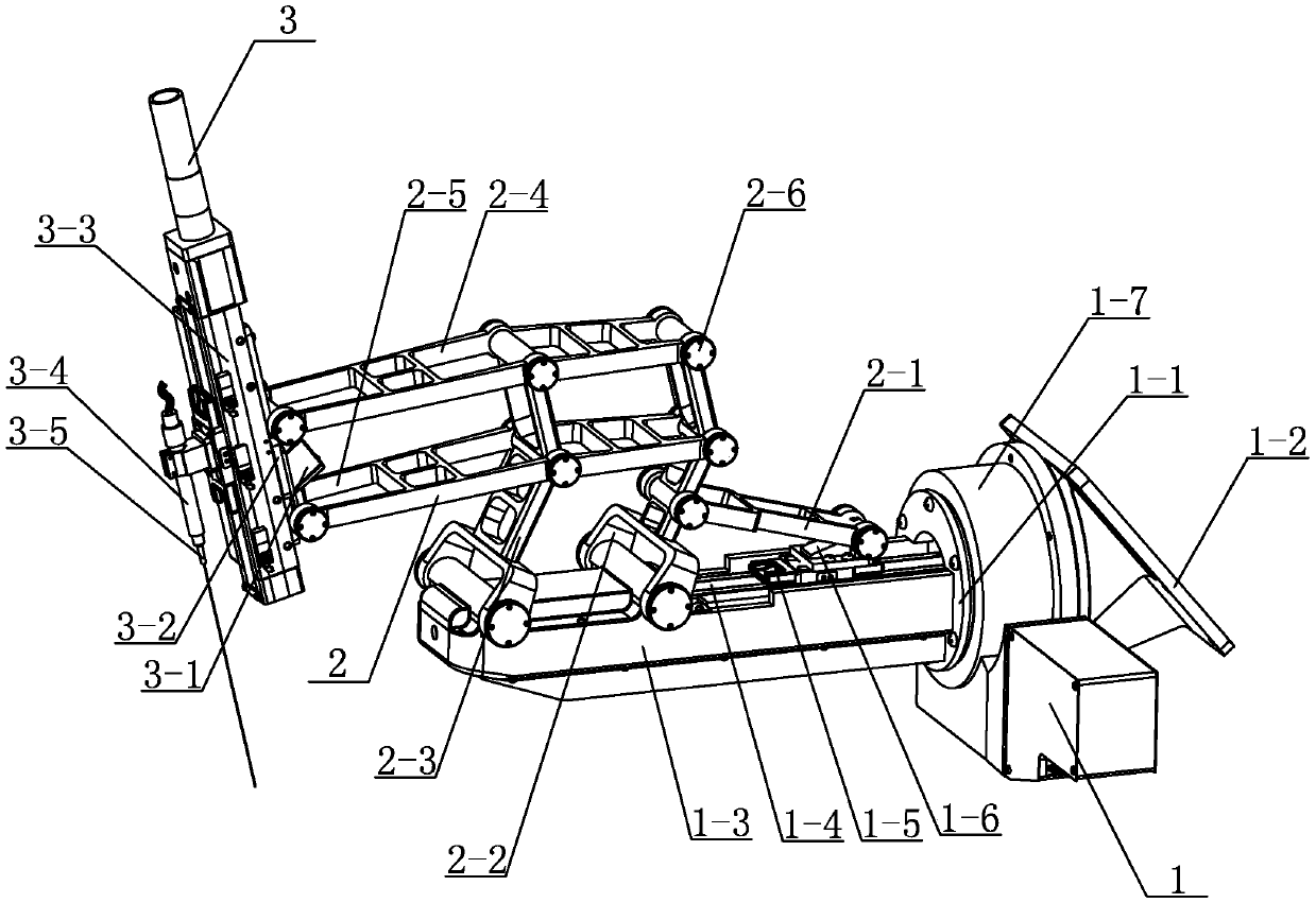
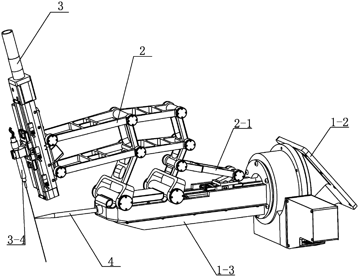
[0026] Specific implementation mode one: combine Figure 1 to Figure 2 Describe this embodiment, in order to more clearly show how the RCM point calibration method of the present invention is realized, the specific structure of the ophthalmic microsurgery auxiliary robot actuator that the present invention adopts when calibrating is disclosed as follows:

[0027] An executive mechanism of an ophthalmic microsurgery auxiliary robot in this embodiment includes a cantilever rotation module 1; it also includes a link assembly 2 and an end effector assembly 3, and the cantilever rotation module 1 includes a rotation module 1-1, Seat 1-2, cantilever 1-3, cantilever linear guide module 1-4, cantilever slider 1-5, cantilever slider connector 1-6 and rotating module shell 1-7, one end of cantilever base 1-2 is connected with The external mobile device is connected, the other end of the cantilever base 1-2 is connected to the rotating module 1-1, the cantilever 1-3 is connected to the r...

specific Embodiment approach 2

[0035] Specific implementation mode two: combination figure 1 Describe this embodiment, the rotating module 1-1 of this embodiment comprises motor, transmission device, worm and worm wheel, the output end of motor is connected with transmission device, the output end of transmission device is connected with worm wheel, and worm screw is installed on the cantilever 1-3 Inside, and the worm meshes with the worm gear. Such arrangement drives the rotation of the entire cantilever 1-3 around the cantilever axis; the connection method is simple and reliable, and other components and connection relations are the same as those in the first embodiment.

specific Embodiment approach 3

[0036] Specific implementation mode three: combination figure 1 This embodiment will be described. The cantilever linear guide module 1-4 of this embodiment adopts the XYZ Cartesian coordinate system of the KK60-10P-300A-F2ES2 (PNP) model. With such arrangement, the stroke is large, the production is convenient, and the cost is low. Other compositions and connections are the same as those in Embodiment 1 or 2.


PUM


Abstract

The invention relates to a calibration method of an ophthalmic microsurgery auxiliary robot, and relates to the calibration method of the auxiliary robot. The present invention aims to solve the problem of complicated algorithm and difficult operation calibration of RCM point calibration method of ophthalmic microsurgery robots in the prior art. The invention comprises the following steps: step 1:mounting calibration needle horizontally on the longitudinal end of a cantilever of a cantilever rotation module; step 2: mounting a surgical syringe on a slide block on an end effector linear guiderail module; step 3: adjusting the position of the syringe and the patient's eye; step 4: RCM point calibration: allowing the end effector linear guide rail module to drive the surgical syringe to move from the lower right to the upper left first, stopping the motor action immediately when a photoelectric switch detects the proximity signal of the slide block, allowing a motor to rotate reversely,allowing the surgical syringe to move from the upper left to the lower right, stopping moving after detecting contact between the syringe and the calibration needle, and recording the pulse number ofa grating ruler so as to finish calibration; and step 5: the disassemblyof the calibration needle. The method is used for fundus microsurgery.

Description

technical field [0001] The invention relates to an auxiliary robot calibration method, in particular to an ophthalmic microsurgery auxiliary robot calibration method. Background technique [0002] When using medical robots to perform minimally invasive fundus microsurgery, the difficulty is that the surgical instruments need to penetrate the patient's eyeball from the sclera insertion point, and rotate around the insertion point flexibly without causing the pore membrane to expand to complete the corresponding operation. operate. This rotation point is called RCM, and RCM (English: Remote center of motion) refers to the fixed point. [0003] The accurate construction of RCM plays an important role in reducing the operating accuracy and stability of doctors during surgery. At present, for the problem of how to construct RCM in minimally invasive ophthalmic microsurgery, the motion mechanism under mechanical constraints is mainly used to realize RCM, and active software algo...

Claims


Application Information

Patent Timeline
Patent Type & Authority Applications(China)
IPC IPC(8): A61B34/37
CPCA61B34/37A61B34/70
Inventor 张赫武睿赵杰
Owner HARBIN INST OF TECH
Why Eureka
Try Eureka