Laserstamping forming method and device

A laser stamping and laser technology, applied in the field of laser processing, can solve the problems of affecting the service life of the laser, reducing the speed of sheet metal forming, increasing the difficulty of sheet metal molding, etc., to avoid melting and oxidation, improve forming accuracy, and good The effect of controllability

Active Publication Date: 2019-04-12
ANHUI UNIVERSITY OF TECHNOLOGY
View PDF8 Cites 5 Cited by
  • Summary
  • Abstract
  • Description
  • Claims
  • Application Information

AI Technical Summary

Problems solved by technology

Yao Hongbing et al loaded L with a pulsed laser beam 2 Aluminum plate, the study found that the maximum speed during the forming process of the aluminum plate can be as high as 3700m / s. The severe friction between the high-speed deformed sheet and the air causes the surface temperature of the workpiece to rise sharply. The high temperature melts the surface of the sheet and changes the interior of the sheet. The structural structure reduces the quality of the formed parts; when the sheet is deformed by impact, the air will hinder the forming of the sheet, reducing the speed of the sheet forming, and to overcome the deformation resistance, it is necessary to increase the laser energy, high-energy laser The output will heat up the spectral tube of the laser, which will affect the service life of the laser; especially for the forming of a sheet with a specific shape, such as a pointed shaped part, as the air gathers in a local position, as the deformation gradually increases, making The air pressure in the local area of ​​the mold cavity is getting higher and higher, which increases the difficulty of attaching the sheet to the mold, and even causes the reverse deformation of the sheet, which greatly reduces the forming accuracy of the sheet

Method used


Image

  • Laserstamping forming method and device
  • Laserstamping forming method and device
  • Laserstamping forming method and device

Examples


Embodiment Construction

[0021] The technical details proposed by the present invention will be described in detail below with reference to the accompanying drawings.

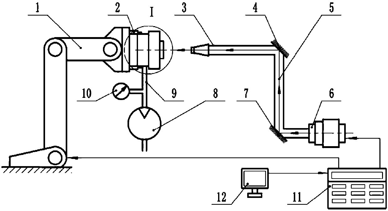
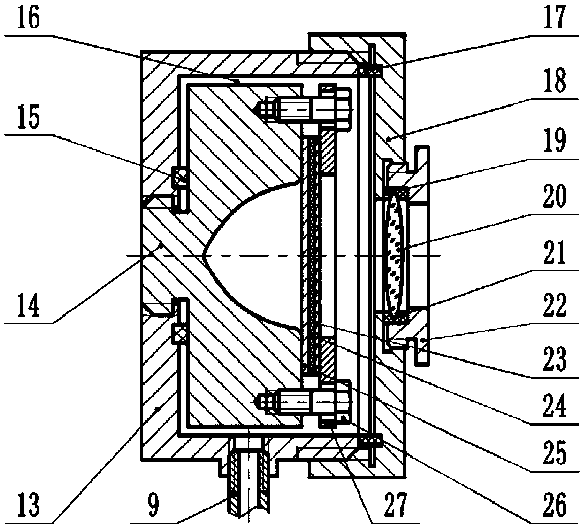
[0022] The device of the present invention includes a laser 6, a light guide system, a workpiece mold system, and a control system; the light guide system includes a light guide tube 3, a pulsed laser beam 5, a first total reflection mirror 7, a second total reflection mirror 4, a converging lens 20, Optical glass 23; one end of the light pipe 3 is connected to the laser 6, and the first total reflection mirror 7 and the second total reflection mirror 4 are connected in turn, the first total reflection mirror 7 and the second total reflection mirror 4 Mainly to change the propagation direction of the pulsed laser beam 5, the outlet of the light pipe 3 is facing the converging lens 20, the axis of the light pipe 3 coincides with the axis of the converging lens 20 and the symmetrical center line of the metal sheet 25; the workpiece mold s...


PUM

PropertyMeasurementUnit
thicknessaaaaaaaaaa
thicknessaaaaaaaaaa

Abstract

The invention discloses a laser stamping forming method and device, and belongs to the technical field of laser processing. The laser stamping formingdevice comprises a laser, a light guide system, aworkpiece die system and a control system. According to the laser stamping forming method, first a plate and a die are placed in a sealed cavity, a vacuum pump is used forpumping air out from the sealed cavity, so that a close-to-vacuum state is formed in a die cavity, and then the plate is formed by using laser-induced shock waves. The laser stamping forming method and device have simple equipment and donot need complicated dies,flexible processing can be realized by controlling the position of a manipulator, processing parameters are good in controllability, safe and reliable operation is achieved, and the laser stamping forming method and device have potential market application value.

Description

Technical field: [0001] The invention belongs to the field of laser processing, and in particular relates to a laser stamping forming method and device. The method and device of the present invention are used to press and form the sheet metal by utilizing the mechanical force of the laser-induced plasma to form a high-pressure shock wave in a near-vacuum state, and are especially suitable for the precision forming of the sheet material that is difficult to process by conventional methods. Background technique: [0002] Laser shock forming technology is a new technology that uses the force effect of laser-induced high-amplitude shock waves to cause plastic deformation of sheets. Laser shock forming technology not only effectively overcomes the springback problem of sheets during shock forming, but also has , materials with strain rates up to 10 6 / s or more effectively increases the formability of the material itself, therefore, this technology can form metal materials that ...

Claims


Application Information

Patent Timeline
Patent Type & Authority Applications(China)
IPC IPC(8): B21D26/06
CPCB21D26/06
Inventor 张兴权纪啸天牛文武张义伟戚晓利裴善报左立生
Owner ANHUI UNIVERSITY OF TECHNOLOGY
Why Eureka
Try Eureka