High precision machining apparatus used for electronic equipment outer shell

A technology for high-precision machining and electronic equipment, applied in metal processing equipment, grinding/polishing equipment, manufacturing tools, etc., can solve problems such as inability to identify, low processing efficiency, time-consuming and labor-intensive, and save materials and improve production. Efficiency, the effect of ensuring imaging precision and accuracy

Inactive Publication Date: 2019-04-12
苏州丰川电子科技有限公司
View PDF13 Cites 2 Cited by
  • Summary
  • Abstract
  • Description
  • Claims
  • Application Information

AI Technical Summary

Problems solved by technology

However, on each workpiece, the area that needs to be polished is often only in a local area, because the grinding device cannot identify the local area that needs to be polished, and the local grinding can only be achieved through comprehensive grinding, which is time-consuming and labor-intensive, and the processing efficiency is low.

Method used


Image

  • High precision machining apparatus used for electronic equipment outer shell
  • High precision machining apparatus used for electronic equipment outer shell
  • High precision machining apparatus used for electronic equipment outer shell

Examples


Embodiment 1

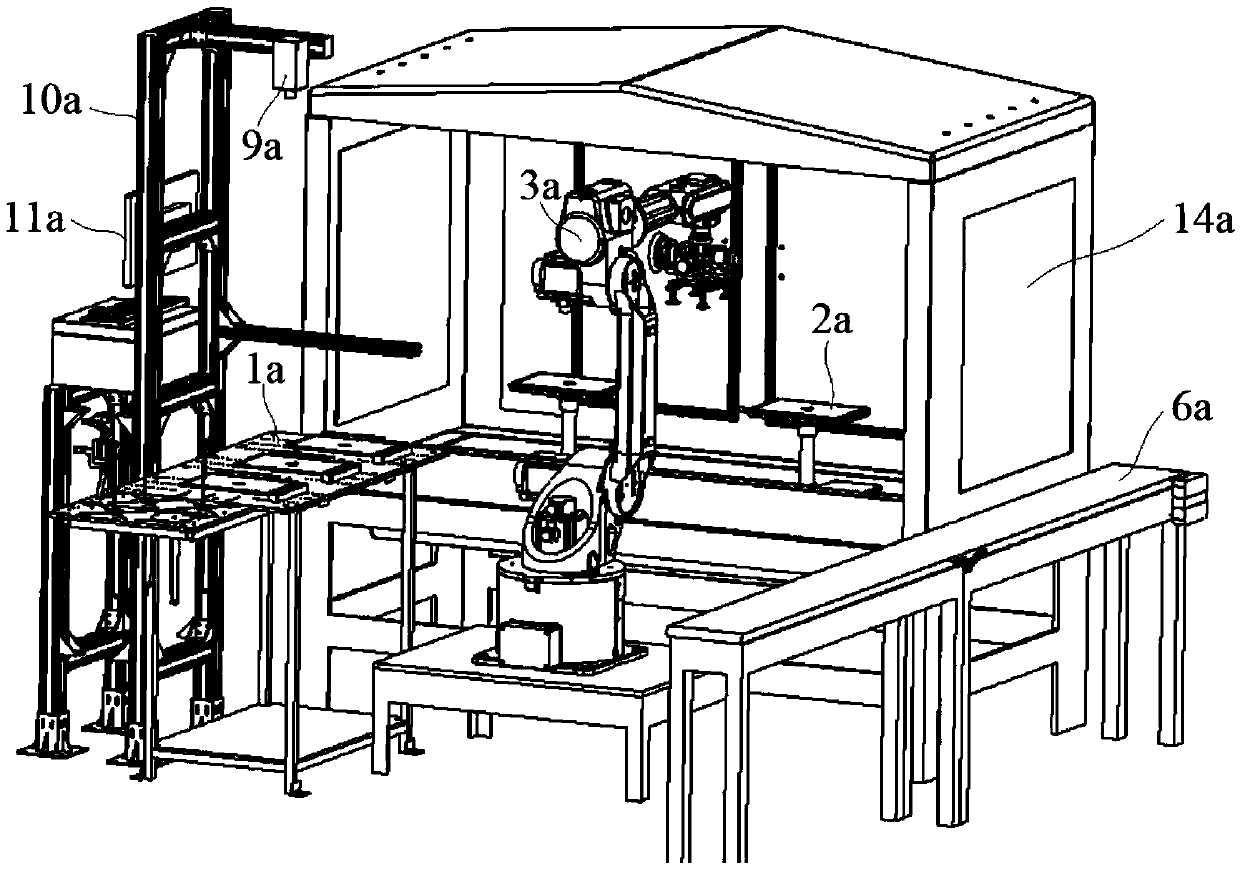
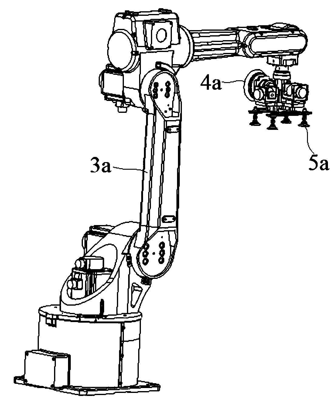
[0036] Embodiment 1: A high-precision processing device for electronic equipment casings, including a feeding support 1a, a grinding support 2a, a number of mechanical arms 3a, a grinding head 4a and a material delivery fixture 5a, and the grinding head 4a and transportation The material clamps 5a are installed and connected to the end nodes of the mechanical arm 3a respectively, and the feeding support 1a and the grinding support 2a are respectively arranged along the circumference of the mechanical arm 3a;

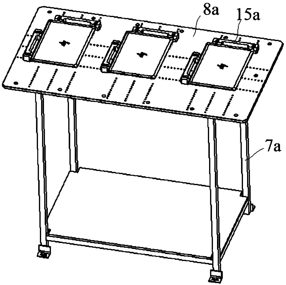
[0037]Described loading support 1a comprises support 7a and the loading table 8a that is installed on the support 7a, and described loading table 8a has an imaging mechanism 9a on the side opposite to mechanical arm 3a, and this imaging mechanism 9a is installed on a The upper end of the mounting frame 10a is located above the loading table 8a, and the grinding support 2a includes a base 12a and several grinding tables 13a connected to the upper surface of the base 12a; ...

Embodiment 2

[0045] Embodiment 2: A high-precision processing device for electronic equipment casings, including a feeding support 1a, a grinding support 2a, a number of mechanical arms 3a, a grinding head 4a and a material delivery fixture 5a, and the grinding head 4a and transportation The material clamps 5a are installed and connected to the end nodes of the mechanical arm 3a respectively, and the feeding support 1a and the grinding support 2a are respectively arranged along the circumference of the mechanical arm 3a;

[0046] Described loading support 1a comprises support 7a and the loading table 8a that is installed on the support 7a, and described loading table 8a has an imaging mechanism 9a on the side opposite to mechanical arm 3a, and this imaging mechanism 9a is installed on a The upper end of the mounting frame 10a is located above the loading table 8a, and the grinding support 2a includes a base 12a and several grinding tables 13a connected to the upper surface of the base 12a; ...


PUM


Abstract

The invention discloses a high precision machining apparatus used for an electronic equipment outer shell. The high precision machining apparatus used for the electronic equipment outer shell comprises a feeding supporting seat, a polishing supporting seat, a plurality of mechanical arms, a polishing head and a material conveying clamping fixture, the polishing head and the material conveying clamping fixture are correspondingly connected with the tail end nodes of the mechanical arms in an installing mode, the feeding supporting seat and the polishing supporting seat are arranged in the circumferential direction of the mechanical arms, the feeding supporting seat comprises a supporting frame and a feeding table installed on the supporting frame, the tail-end nodes of the mechanical arms are connected with an installing seat, the polishing head and the material conveying clamping fixture are installed on the installing seat, an air outlet communicates with a second cavity body, the lower end of a core body is connected with a rotating shell, the central axes of the installing seat, a bearing and a rotating head coincide, and the central axis of the rotating head does not coincide with the central axis of the core body. According to the high precision machining apparatus used for the electronic equipment outer shell, vacuum adsorption of a workpiece is realized through an adsorption hole and an adsorption line groove, the accurate position and stability of the workpiece are ensured in the polishing process, the situations of offset and the like in the polishing process are avoided, and the polishing accuracy and stability are ensured.

Description

technical field [0001] The invention relates to a high-precision processing device used for electronic equipment shells, and belongs to the technical field of processing precision parts of electronic products. Background technique [0002] At present, most of the appearance structural parts / accessories of mobile phones and laptops on the market are made of metal materials. The forming of metal materials mainly includes aluminum extrusion, die-casting, forging and other methods. No matter which forming method is used, CNC machining centers are required for processing after forming. Due to the existence of poor appearance such as knife marks and scratches in the CNC machining process, a series of appearance retreatments such as passivation, grinding and polishing, spraying, and anodic oxidation must be carried out on the workpiece. However, on each workpiece, the area that needs to be polished is often only in a local area, because the grinding device cannot identify the local...

Claims


Application Information

Patent Timeline
Patent Type & Authority Applications(China)
IPC IPC(8): B24B41/00B24B49/00B24B41/06
CPCB24B41/00B24B41/005B24B41/06B24B49/00
Inventor 赵长亮周士升蒋燕詹淳崵
Owner 苏州丰川电子科技有限公司
Why Eureka
Try Eureka