Hybrid coupling module and hybrid system

A hybrid power system and hybrid power technology, which is applied to the arrangement of multiple different prime movers of power plants, general power plants, and pneumatic pressure power plants, etc. Transforming hybrid vehicles and other issues to achieve the effect of simple structure and space saving

Active Publication Date: 2020-04-10
哈工大机器人(岳阳)军民融合研究院
View PDF8 Cites 0 Cited by
  • Summary
  • Abstract
  • Description
  • Claims
  • Application Information

AI Technical Summary

Problems solved by technology

[0005] The technical problem to be solved by the present invention is to solve the problem that the existing hybrid power coupling device and hybrid power system are complex in structure and too large in size, and are not suitable for transforming traditional vehicles into hybrid vehicles

Method used


Image

  • Hybrid coupling module and hybrid system
  • Hybrid coupling module and hybrid system
  • Hybrid coupling module and hybrid system

Examples


Embodiment 1

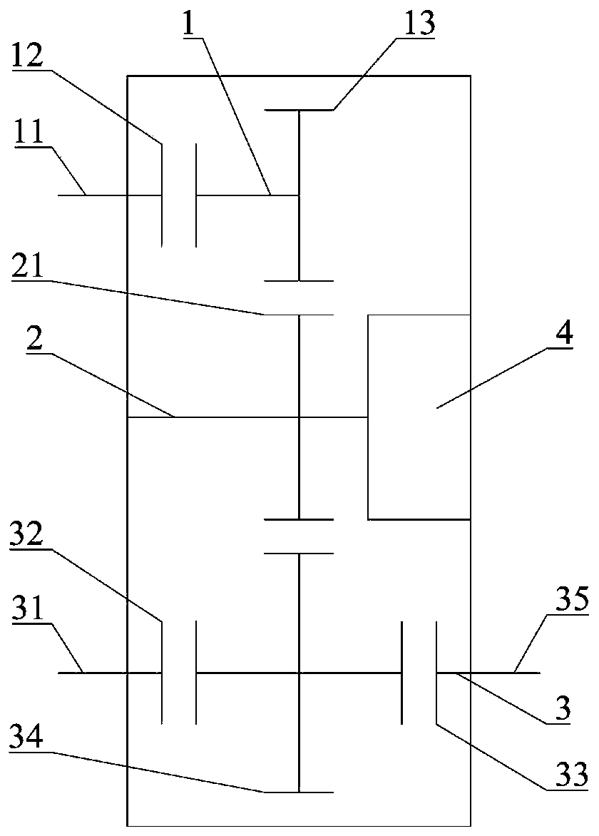
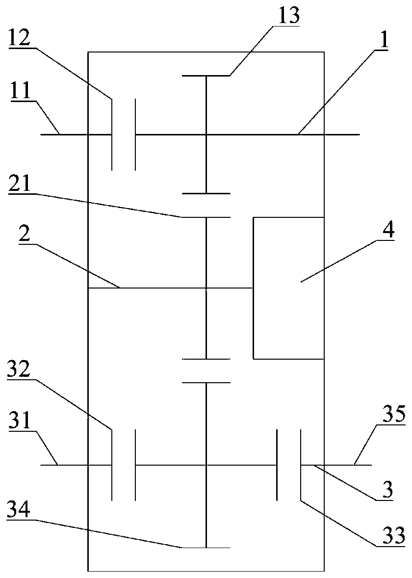
[0042] Such as figure 1 As shown, a hybrid coupling module provided by an embodiment of the present invention includes an auxiliary generator 4, and a first shaft 1, a second shaft 2 and a third shaft 3 arranged in parallel and spaced apart. Wherein, one end of the first shaft 1 is the drive motor input end 11, which is used to connect with the output end of the drive motor 5 that provides vehicle power. The first shaft 1 is provided with a first clutch 12 and a first gear 13, and the first gear 13 covers It is arranged on the first shaft 1 and can rotate coaxially with the first shaft 1 . The first clutch 12 is arranged between the first gear 13 and the input end 11 of the driving motor. That is, the first clutch 12 will

[0043] The first shaft 1 is divided into the first section and the second section coaxially arranged, the first section first shaft 1 is connected with the output end of the driving motor 5, and rotates synchronously with the output end of the driving moto...

Embodiment 2

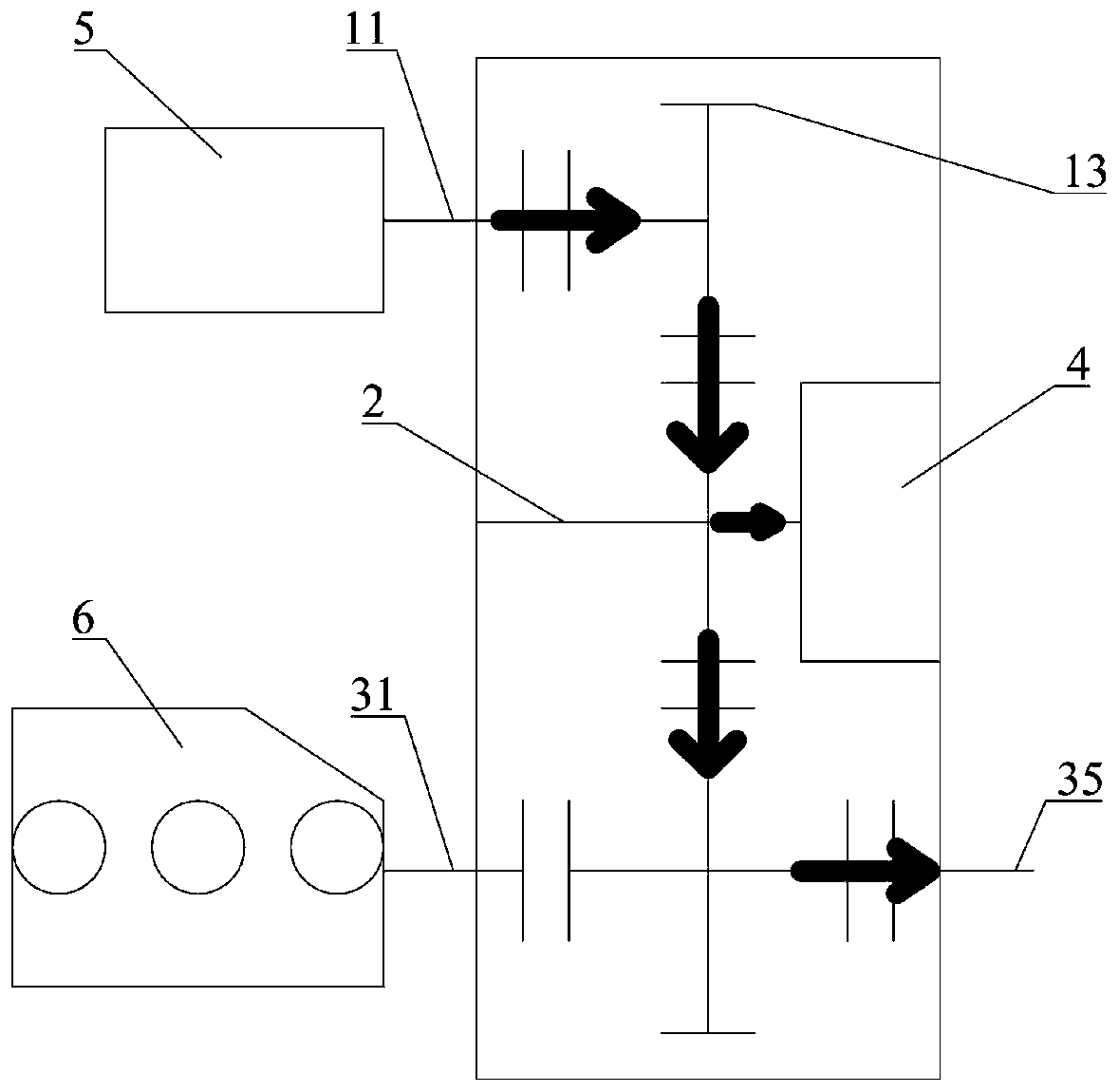
[0054] The second embodiment provides a hybrid power system, including a drive motor 5, an engine 6, a control module, and any one of the hybrid coupling modules described above.

[0055] Wherein, the output end of drive motor 5 is connected with the drive motor input end 11 of the first shaft 1 in the hybrid power coupling module; the output end of engine 6 is connected with the engine input end 31 of the third shaft 3 in the hybrid power coupling module; control module It is connected with the hybrid coupling module, the drive motor 5 and the engine 6, and is used to receive user instructions, or make comprehensive judgments based on information such as the remaining power of the vehicle and the vehicle speed, and send control instructions to the hybrid coupling module, the drive motor 5 and the engine 6, The hybrid power system is controlled to work in different working modes.

[0056] The hybrid power system provided by the invention has strong functionality, can realize m...


PUM


Abstract

The invention relates to a hybrid power coupling module which comprises an auxiliary power generator, a first shaft, a second shaft and a third shaft, wherein the first shaft, the second shaft and thethird shaft are arranged in parallel at intervals; one end of the first shaft is a driving motor input end; a first clutch and a first gear are arranged at the first shaft; the first clutch is arranged between the first gear and the input end of the driving motor; the second shaft is sleeved by the second gear; the second gear is meshed with the first gear; one end of the second shaft is connected with the output end of the auxiliary power generator; one end of the third shaft is the input end of an engine; the other end of the third shaft is a module output end; the third shaft is provided with a second clutch, a third clutch and a third gear; the third gear is meshed with the second gear; the second clutch is arranged between the third gear and the input end of the engine; the third clutch is arranged between the third gear and the module output end. The module is simple in structure, multiple working modes can be achieved through control on the clutch, and the module can be used asa key component of a hybrid power automobile and is particularly applicable to improvement of a hybrid power automobile from a conventional automobile.

Description

technical field [0001] The invention relates to the technical field of hybrid electric vehicles, in particular to a hybrid power coupling module and a hybrid power system. Background technique [0002] As a new energy vehicle, hybrid electric vehicles have broad application prospects. Existing hybrid vehicles are generally transformed on the basis of traditional vehicles, with a traditional internal combustion engine as the main power source, and a drive motor as the auxiliary power source. After power coupling, hybrid power output is realized. Common hybrid vehicle power coupling methods include torque coupling, speed coupling, and both torque coupling and speed coupling. Hybrid drive makes the engine work in a high-efficiency zone, which greatly improves fuel economy compared with traditional vehicles. performance, reducing pollutant emissions. [0003] But at present, the existing power coupling devices on the market usually have the disadvantages of complex structure, ...

Claims


Application Information

Patent Timeline
Patent Type & Authority Patents(China)
IPC IPC(8): B60K6/365B60K6/38
CPCB60K6/365B60K6/38
Inventor 栾志博衣运豪李建英
Owner 哈工大机器人(岳阳)军民融合研究院
Why Eureka
Try Eureka