Welding strip annealing device and annealing method

A technology of annealing device and welding strip, applied in the direction of coating, furnace type, furnace, etc., can solve the problems of insufficient annealing, unstable contact, easy overheating and burnout, etc. full effect

Pending Publication Date: 2019-04-12
XIAN TELISON NEW MATERIAL
View PDF0 Cites 3 Cited by
  • Summary
  • Abstract
  • Description
  • Claims
  • Application Information

AI Technical Summary

Problems solved by technology

[0004] However, if the annealing method is used for triangular, round, embossed, and reflective ribbons, the wires will pass through most of the swing rods and driving wheels, and the contact between the ribbon and the surface of the lower annealing wheel will be unstable, and slipping and sparking will easily occur. Phenomenon
In addition, during the high-speed production process, an obvious tension is formed on the soft wire in the annealing area. On the one hand, the wire will be stretched and deformed due to the force, the resistance will increase, and it will be easily blown by overheating; voltage, insufficient annealing, the yield strength of the wire can not be well reduced

Method used


Image

  • Welding strip annealing device and annealing method
  • Welding strip annealing device and annealing method
  • Welding strip annealing device and annealing method

Examples


Embodiment Construction

[0029] The following will clearly and completely describe the technical solutions in the embodiments of the present invention with reference to the accompanying drawings in the embodiments of the present invention. Obviously, the described embodiments are only some, not all, embodiments of the present invention.

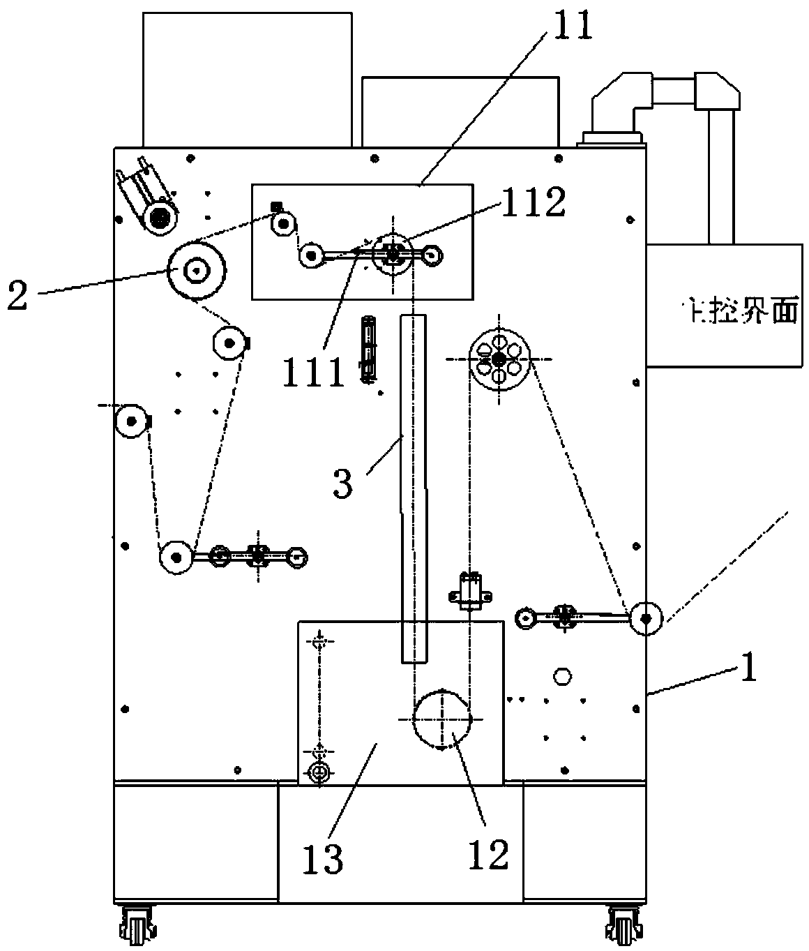
[0030] refer to figure 2 , figure 2 It is a conventional ribbon annealing device, which includes an upper annealing wheel 2 and a lower annealing wheel 12 arranged in a cooling water tank 13. A cycloidal mechanism 11 is arranged between the annealing wheel 2 and the lower annealing wheel 12, and the cycloidal mechanism 11 has a swing lever 111 and a driving wheel 112 in the majority, and the swing lever 111 can adjust the speed of the lower annealing wheel 12. When triangular, circular, embossed, reflective and other welding ribbons and wires adopt conventional welding ribbon annealing devices, because the welding ribbons and wires pass through too many swing bars...


PUM

PropertyMeasurementUnit
diameteraaaaaaaaaa
yield strengthaaaaaaaaaa

Abstract

The invention discloses a welding strip annealing device. The device comprises a box body, an upper annealing wheel, a glass tube, a saline solution pond, and a passive line passing wheel are arrangedin the box body, the lower end of the glass tube extends into the saline solution pond, the passive line passing wheel is arranged in the saline solution pond. The invention further discloses an annealing method. On the basis of the welding strip annealing device, a saline solution is arranged in the saline solution pond, the upper annealing wheel serves as a positive electrode, the saline solution serves as the negative electrode, the welding strip wire rod passes through the upper annealing wheel and enters the glass tube, and then passes through the glass tube to be immersed in the salinesolution, the positive electrode of the upper annealing wheel and the negative electrode of the saline solution are powered on and pressurized on the two ends of the welding strip wire rod, the welding strip wire rod is heated, and annealing is finished. The annealing device and the annealing method solve the problems that the welding strip is unstable in contact, and prone to slippage and ignition, meanwhile, stress of a cycloid mechanism on the welding strip wire rod can be reduced, the two ends of the electrodes can be charged with higher voltage, annealing is sufficient, and the wire rod yield strength can be effectively reduced.

Description

technical field [0001] The invention relates to the technical field of annealing, in particular to an annealing device and an annealing method for welding strips, which are mainly applicable to welding strips with triangular, round, embossed and reflective shapes. Background technique [0002] Photovoltaic ribbon is mainly an important welding material in the production process of solar cells, which plays the role of connecting and conducting electricity. The quality of the ribbon directly affects the power of the photovoltaic module. The main process is the wire after drawing and calendering, and the surface is tin-coated. In the process of cold rolling and other processing processes, the wire generates stress, and the cold hardening increases the strength of the wire. If the wire is directly put into the tin furnace for surface tin coating, it will cause deformation or distortion of the wire. Therefore, annealing is generally used. Ways to eliminate the stress of the wire...

Claims


Application Information

Patent Timeline
Patent Type & Authority Applications(China)
IPC IPC(8): C21D1/26C21D1/40C21D9/62C21D1/74C22F1/08C23C2/08C23C2/38
CPCC21D1/26C21D1/40C21D1/74C21D9/62C22F1/08C23C2/08C23C2/38
Inventor 罗航温斌常天福董文卫陈庆谊
Owner XIAN TELISON NEW MATERIAL
Why Eureka
Try Eureka