Efficient tea leaf drying device

A tea drying device and high-efficiency technology, applied in the directions of tea drying, drying, drying machine, etc., can solve the problems of slow drying speed, difficult uniform contact, and accumulation of tea leaves, so as to achieve sufficient drying and improve drying efficiency. Effect

Active Publication Date: 2019-04-12
徐州青钱柳农业科技有限公司
View PDF10 Cites 18 Cited by
  • Summary
  • Abstract
  • Description
  • Claims
  • Application Information

AI Technical Summary

Problems solved by technology

[0003] During the production process of tea leaves, it needs to be dried, but the existing tea leaves only use the stirring drying method, so that when drying, due to the distance between the stirring rods, some tea leaves will accumulate, and it is difficult to fully mix with the hot air. Uniform contact resulting in slower drying

Method used


Image

  • Efficient tea leaf drying device
  • Efficient tea leaf drying device
  • Efficient tea leaf drying device

Examples


Embodiment 1

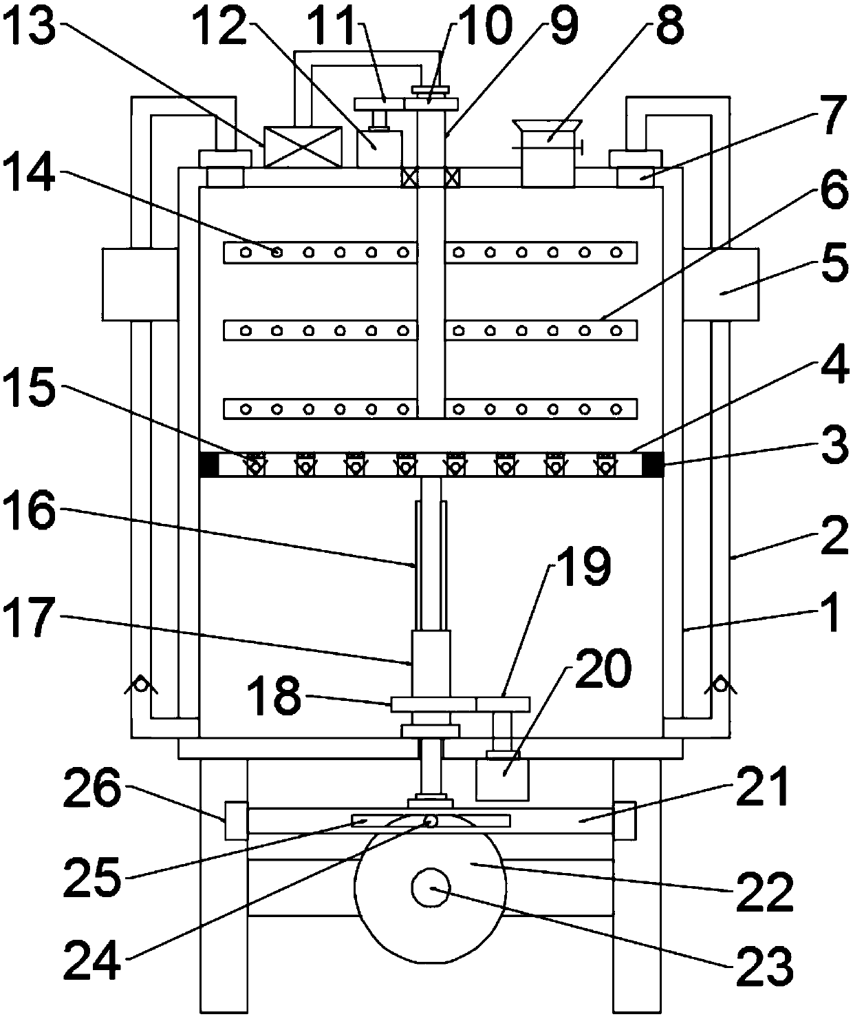
[0021] see Figure 1-2 , in an embodiment of the present invention, a high-efficiency tea drying device includes a cylinder body 1, a hot air blower 13, a hollow stirring shaft 9 and a hollow stirring rod 14, and support plates are installed on both sides of the bottom of the cylinder body 1, and the cylinder body 1 A feed hopper 8 is installed on one side of the top, and a valve is installed on the feed hopper 8. A drum door is installed on the upper part of the cylinder body 1 through hinges and buckles. Sealing strips are adhered around the cylinder door. The hollow stirring shaft 9 is rotationally connected with the top of the cylinder body 1 through bearings. The hollow stirring shaft 9 is located on the shaft section inside the cylinder body 1 and is welded and fixed with a plurality of hollow stirring rods 6. The surface of the hollow stirring rods 6 is uniformly provided with A plurality of air jet pores 14, the hot air blower 13 is installed on the top of the cylinder...

Embodiment 2

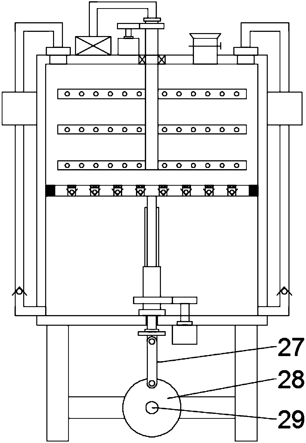
[0023] see image 3, the difference between this embodiment and Embodiment 2 is that the first driving mechanism is replaced by a second driving mechanism, and the second driving mechanism includes a fourth motor 29, a second disk 28 and a connecting rod 27, and the first driving mechanism Four motors 29 are installed on the support plate by the mounting plate, the output shaft end of the fourth motor 29 is equipped with a second disc 28, the outer side of the front end of the second disc 28 is hinged with a connecting rod 27, and the other end of the connecting rod 27 is hinged with a The fixed plate, the bottom end of the spline shaft 16 is rotationally connected with the fixed plate through a bearing and a bearing seat, the fourth motor 29 is started, and the fourth motor 29 drives the second disc 28 to rotate, and the second disc 28 is driven by the connecting rod 27 The spline shaft 16 moves up and down.

[0024] The working principle of the present invention is: when th...


PUM


Abstract

The invention discloses an efficient tea leaf drying device and relates to the technical field of tea production. The efficient tea leaf drying device aims at solving the problems that an existing device causes tea leaf accumulation and is low in drying speed. The efficient tea leaf drying device comprises a barrel body, a hot air blower, a hollow stirring shaft and hollow stirring rods. A pistondisc is mounted at the position, located below the hollow stirring shaft, inside the barrel body. The bottom end of a spline shaft is provided with a first driving mechanism. The first driving mechanism comprises a third motor, a disc and a movable rod. An air suction pipe is connected to an exhaust opening. The other end of the air suction pipe communicates with the bottom of an inner chamber ofthe barrel body. The piston disc is uniformly provided with multiple air outlet through holes. A one-way valve is mounted in each air outlet through hole. The efficient tea leaf drying device is provided with the hollow stirring shaft, the hollow stirring rods, the hot air blower, the piston disc, the spline shaft, a sleeve and the first driving mechanism; tea leaves are dried while being stirred;drying is conducted more thoroughly and more uniformly; the drying efficiency is improved; drying vapor is continuously pumped out through the piston disc, and after drying, the tea leaves are driedfrom the bottom in a whirlwind manner; and the drying efficiency is further improved.

Description

technical field [0001] The invention relates to the technical field of tea production, in particular to a high-efficiency tea drying device. Background technique [0002] Tea refers to the leaves or buds of the tea tree. Generally speaking, tea refers to a beverage that is processed from the leaves of the tea tree and can be drunk directly with boiling water. Tea is a dicotyledon, about 30 genera and 500 species, distributed in tropical and subtropical regions. There are 14 genera and 397 species in China, and they are mainly produced in the south of the Yangtze River. Among them, Tea and Heshu are of great economic value. Tea contains catechin, cholesterolenone, caffeine, inositol, folic acid, pantothenic acid and other ingredients, which can improve human health. [0003] During the production process of tea leaves, it needs to be dried, but the existing tea leaves only use the stirring drying method, so that when drying, due to the distance between the stirring rods, s...

Claims


Application Information

Patent Timeline
Patent Type & Authority Applications(China)
IPC IPC(8): F26B11/14F26B21/00F26B21/08F26B25/02F26B25/04A23F3/06
CPCA23F3/06F26B11/14F26B21/001F26B21/004F26B21/005F26B21/08F26B25/02F26B25/04F26B2200/20
Inventor 尹领
Owner 徐州青钱柳农业科技有限公司
Why Eureka
Try Eureka