
High explosion pressure simulation device for fatigue test of piston components

A technology for fatigue testing and piston components, which is applied in the testing of mechanical components, testing of machine/structural components, measuring devices, etc. It can solve the problem of insufficient verification and assessment capabilities of high-load piston fatigue strength, and the simulation pressure is greatly affected by equipment capabilities. The problem of single load action, etc., achieves the effect of improving the repeated utilization rate, low working strength of the equipment, and high test load.

Active Publication Date: 2020-11-06
CHINA NORTH ENGINE INST TIANJIN
View PDF10 Cites 0 Cited by
  • Summary
  • Abstract
  • Description
  • Claims
  • Application Information

AI Technical Summary

Problems solved by technology

The disadvantages are low test frequency, lack of thermal influence, and single load effect
In addition, the piston fatigue test device is simply connected to the electro-hydraulic servo system, and the simulated pressure is greatly affected by the capability of the equipment, which restricts the application of test pressure with a high safety factor under high explosion pressure, and the ability to verify and assess the fatigue strength of high-load pistons is insufficient

Method used


Image

  • High explosion pressure simulation device for fatigue test of piston components
  • High explosion pressure simulation device for fatigue test of piston components
  • High explosion pressure simulation device for fatigue test of piston components

Examples


Embodiment Construction

[0029] It should be noted that, in the case of no conflict, the embodiments of the present invention and the features in the embodiments can be combined with each other.

[0030] In describing the present invention, it should be understood that the terms "center", "longitudinal", "transverse", "upper", "lower", "front", "rear", "left", "right", " The orientations or positional relationships indicated by "vertical", "horizontal", "top", "bottom", "inner" and "outer" are based on the orientations or positional relationships shown in the drawings, and are only for the convenience of describing the present invention and Simplified descriptions, rather than indicating or implying that the device or element referred to must have a particular orientation, be constructed and operate in a particular orientation, and thus should not be construed as limiting the invention. In addition, the terms "first", "second", etc. are used for descriptive purposes only, and should not be understood ...


PUM


Abstract

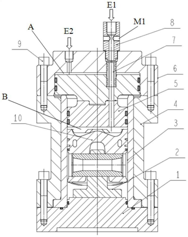
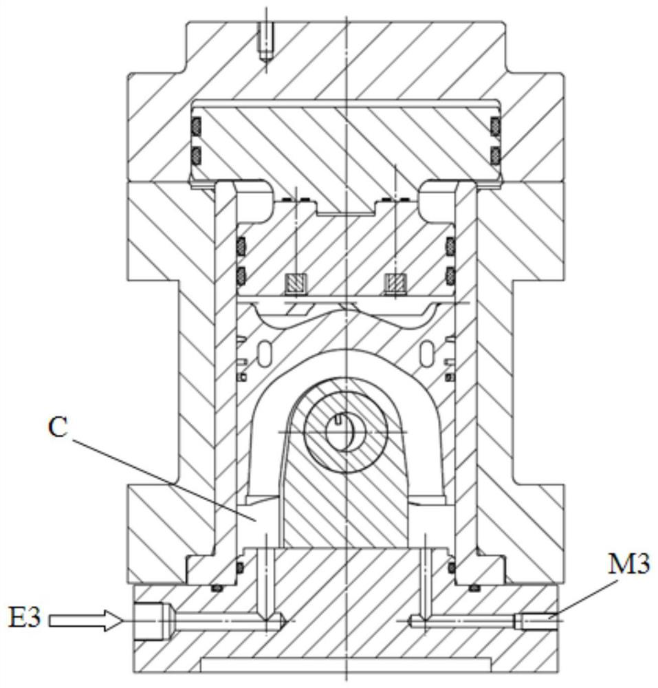
The invention provides a piston part fatigue test high detonation pressure simulating device. The piston part fatigue test high detonation pressure simulating device comprises a test machine seat, a piston supporting seat, an adjusting cylinder sleeve, a test cylinder body, a load amplifier and a low-pressure cavity body, a low-pressure input cavity A is formed between an inner hole of the low-pressure cavity body and the top surface of a low-pressure touching head, a high detonation pressure action cavity B is formed by the bottom surface of a high-pressure touching head, the top surface of atest piston and the adjusting cylinder sleeve, an inertia force action cavity C is formed by the test machine seat, the adjusting cylinder sleeve and the bottom of the test piston, and the low-pressure input cavity A, the high detonation pressure action cavity B and the inertia force action cavity C are separately connected with an electro hydraulic servo system through own oil ducts. According to the piston part fatigue test high detonation pressure simulating device, a test method of three-channel inputting three-oil cavity control is adopted, and oil mass supplement, load infliction and pressure monitoring are separately carried out on three pressure cavities through a three-channel of the electro hydraulic servo system. The working purposes of low-pressure output of the equipment, high load infliction of the test piece head and asynchronous bearing of the bottom and skirt section of the test piece are realized.

Description

technical field [0001] The invention belongs to the technical field of piston testing devices, in particular to a high-explosion pressure simulation device for fatigue testing of piston components. Background technique [0002] As a component part of the engine combustion chamber, the piston is subjected to periodic action of high temperature and high pressure during operation, and its structural strength and fatigue reliability are very important. Especially the top of the piston and the bearing part of the piston pin hole due to overload, overspeed and abnormal working conditions, as well as the explosion pressure and speed increase after the engine is strengthened, the load on the piston is increased, and the piston ring land, pit, piston pin hole and other positions are cracked. . In addition, in the development stage of new products, the weak links of the fatigue strength of the piston structure are found in time, and the feasibility of the verification scheme is often...

Claims


Application Information

Patent Timeline
Patent Type & Authority Patents(China)
IPC IPC(8): G01M13/00
CPCG01M13/00
Inventor 狄建兵侯晔星王根全张丽强王昊闫玮
Owner CHINA NORTH ENGINE INST TIANJIN
Learn More