Visible light positioning method based on a particle swarm optimization extreme learning machine

An extreme learning machine and particle swarm optimization technology, applied in neural learning methods, biological models, instruments, etc., can solve problems such as suboptimal, and achieve the effect of reducing impact, improving positioning accuracy, and simple network structure

Pending Publication Date: 2019-04-12
TIANJIN UNIV
View PDF8 Cites 11 Cited by
  • Summary
  • Abstract
  • Description
  • Claims
  • Application Information

AI Technical Summary

Problems solved by technology

[0005] However, since the extreme learning machine randomly generates input weights and hidden layer thresholds, the positioning

Method used


Image

  • Visible light positioning method based on a particle swarm optimization extreme learning machine
  • Visible light positioning method based on a particle swarm optimization extreme learning machine
  • Visible light positioning method based on a particle swarm optimization extreme learning machine

Examples


Example Embodiment

[0032] Example 1

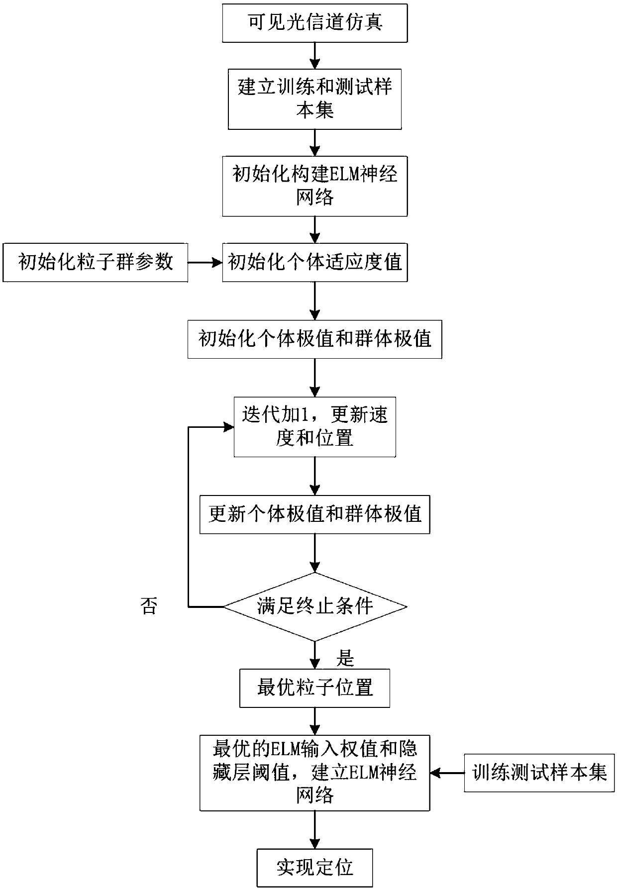
[0033] A visible light positioning method based on particle swarm optimization extreme learning machine, see figure 1 and figure 2 , the method includes the following steps:

[0034] 101: Compare the newly obtained individual fitness value of each particle with the individual extremum Pbest and the group extremum Gbest, and if the new individual fitness value is better, update the individual extremum and the group extremum; when the number of iterations When the maximum value is reached or the fitness value reaches the preset minimum value, the optimal particle is output;

[0035] 102: Use the position of the optimal particle as the input weight of the extreme learning machine and the parameters of the hidden layer threshold;

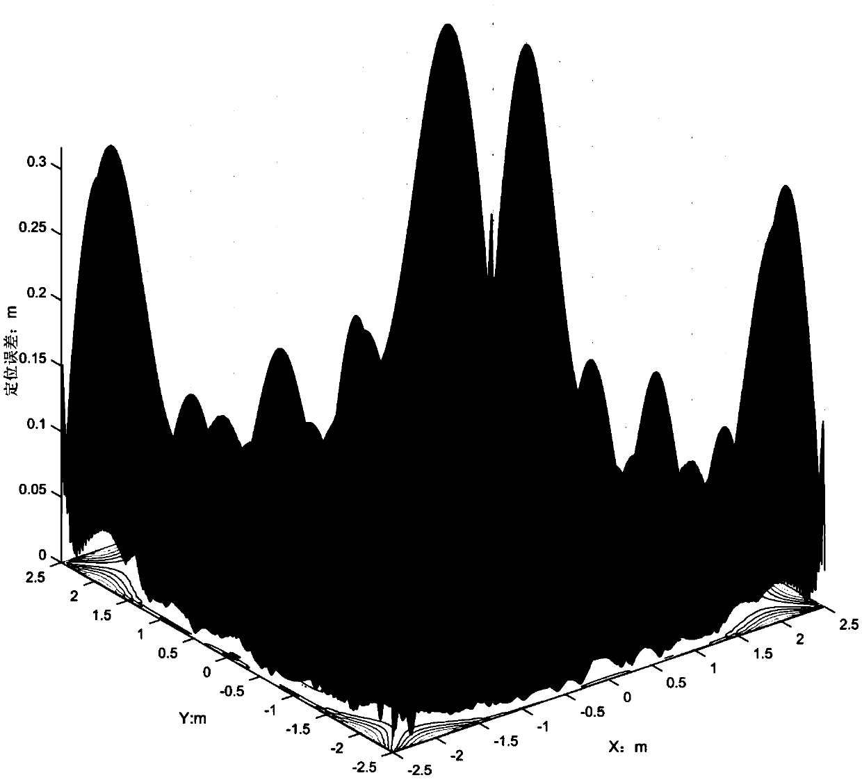
[0036] 103: Input the training sample set into the extreme learning machine neural network for neural network training, input the test sample set into the trained extreme learning machine neural network, and calculate the overall ...

Example Embodiment

[0047] Example 2

[0048] Combine below figure 1 , figure 2 , and specific mathematical formulas further introduce the scheme in embodiment 1, see the following description for details:

[0049] Step 201: Obtain the receiving end power through visible light channel simulation, and the receiving end power can be expressed as:

[0050]

[0051] Among them, P rs is the electric power at the receiving end, P t is the sending power of the LED, R is the conversion rate of the photodetector, H LOS (0) is the line-of-sight propagation DC gain, H ref (0) is the first-order reflected DC gain, is the noise power.

[0052] Specifically, the line-of-sight propagation DC gain can be expressed as:

[0053]

[0054] where A is the physical area of ​​the photodetector, m is the Lambertian order, and D d is the distance between the sending end and the receiving end, φ is the radiation angle, ψ is the incident angle, ψ c is the field of view angle of the receiver, T s (ψ) is t...

Example Embodiment

[0101] Example 3

[0102] Combine below Figure 1-Figure 3 , concrete experimental data carry out feasibility verification to the scheme in embodiment 1 and 2, see the following description for details:

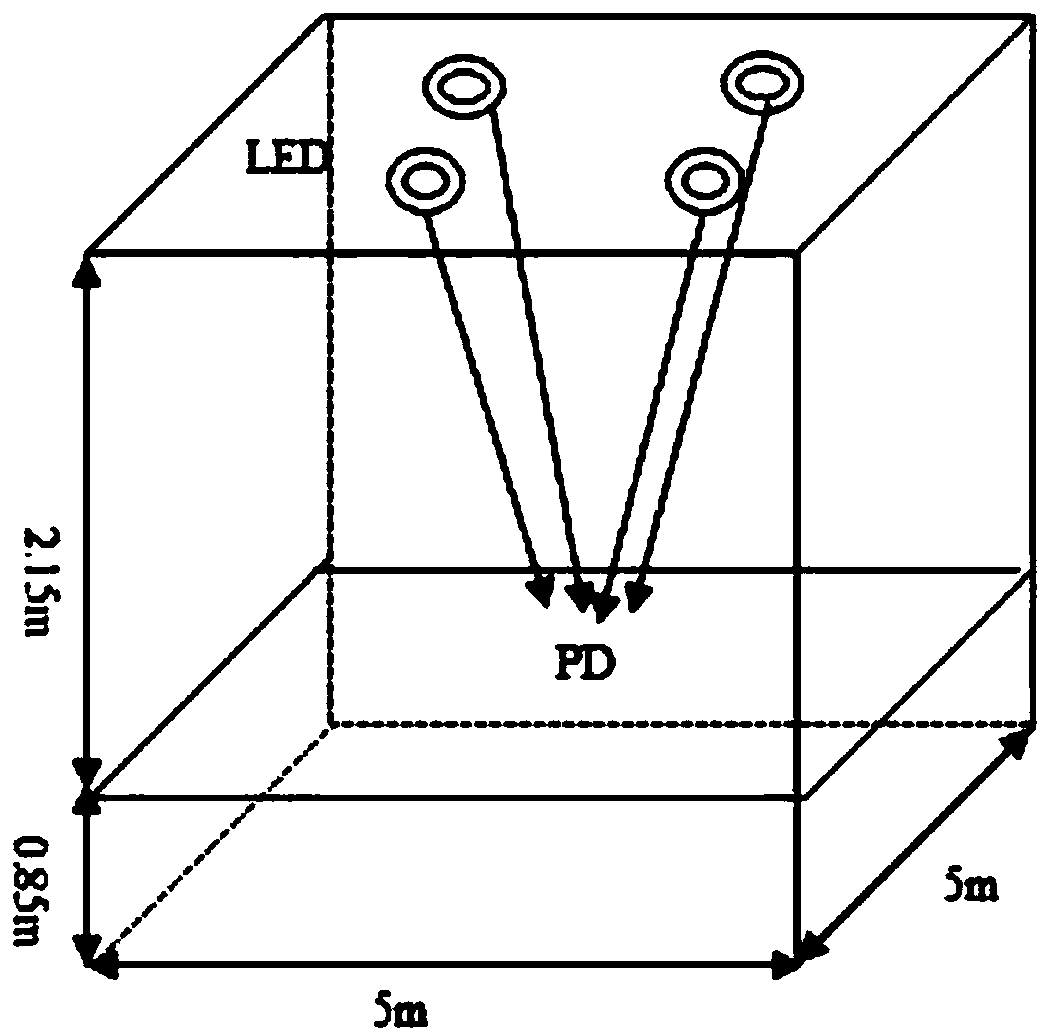
[0103] like figure 1 As shown, 4 LED arrays are located in a room of 5m×5m×3m, the coordinates of the center of the floor are (0,0,0), and the coordinates of the four LEDs are (-1.25,-1.25,3), (1.25,-1.25, 3),(-1.25,1.25,3),(1.25,1.25,3). Each LED array consists of 60×60 LEDs with an emission power of 60mw. The photodetector moves on a plane at a height of 0.85m from the ground, and its area is 1cm 2 . Code and modulate each LED light, send their respective position information, convert the optical signal into an electrical signal at the receiving end photodetector (PD), obtain the electric power at the receiving end, and use the demodulation and decoding method to obtain each LED light respectively. location information.

[0104] like figure 2 As shown, the paramete...


PUM


Abstract

The invention discloses a visible light positioning method based on a particle swarm optimization extreme learning machine, and the method comprises the steps: comparing an individual fitness value and an individual extreme value Pbest of each newly obtained particle with a group extreme value Gbest, and updating the individual extreme value and the group extreme value if the new individual fitness value is better; when the number of iterations reaches a maximum value or the fitness value reaches a preset minimum value, outputting an optimal particle; taking the position of the optimal particle as a parameter of an input weight value and a hidden layer threshold value of an extreme learning machine; inputting the training sample set into an extreme learning machine neural network, carryingout neural network training, inputting the test sample set into the trained extreme learning machine neural network, and calculating an overall average positioning error. According to the method, theextreme learning machine is optimized by using the particle swarm algorithm, so that the extreme learning machine has the advantages of high learning speed, high generalization ability and the like of the extreme learning machine, the defect that the extreme learning machine randomly generates an input weight value and a hidden layer threshold value is overcome, and the network structure is simpler.

Description

technical field [0001] The invention relates to the field of visible light positioning, in particular to a visible light positioning method based on particle swarm optimization extreme learning machine. Background technique [0002] With the application and development of indoor navigation, people's requirements for indoor positioning continue to increase, and positioning technology has also been developed. The GPS technology suitable for outdoor positioning cannot meet the needs of indoor positioning. Other positioning technologies such as ultra-wideband, infrared, and WIFI have not been widely used due to complex equipment, expensive prices, and low positioning accuracy. Visible light communication can be used for data communication, so the application of visible light communication to indoor positioning technology provides a new way for positioning. [0003] According to different receivers, visible light positioning can be divided into two types: photodetector-based and...

Claims


Application Information

Patent Timeline
IPC IPC(8): G06N3/00G06N3/04G06N3/08G01C21/20
CPCG06N3/006G06N3/086G01C21/206G06N3/045
Inventor 徐岩王昕昕
Owner TIANJIN UNIV
Why Eureka
Try Eureka